Charging device butt joint method based on visual mark

A charging device and visual technology, applied in the direction of circuit devices, battery circuit devices, measuring devices, etc., can solve the problems of reducing the convenience of users and not being able to realize the automatic charging of intelligent robots, so as to achieve automatic charging and improve the convenience of use Effect

Active Publication Date: 2016-11-23
北京云迹科技股份有限公司
View PDF5 Cites 17 Cited by
  • Summary
  • Abstract
  • Description
  • Claims
  • Application Information

AI Technical Summary

Problems solved by technology

At present, the charging of intelligent robots is managed manually. For example, during non-working hours, the staff plug in the power supply and charge uniformly.
Or when the power is low during use, the staff plugs in the power to charge it, which cannot realize the automatic charging of the intelligent robot, which reduces the convenience of the user

Method used


Image

  • Charging device butt joint method based on visual mark
  • Charging device butt joint method based on visual mark
  • Charging device butt joint method based on visual mark

Examples


Embodiment 1

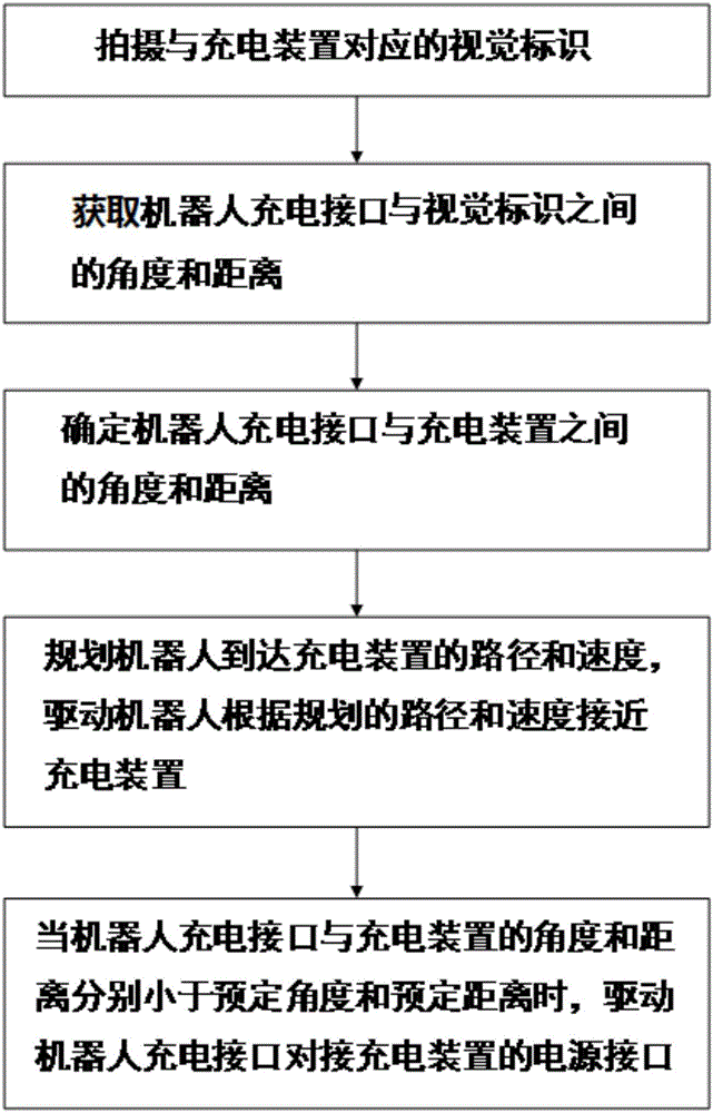
[0018] figure 1 A flow chart of a method for visually identifying a docking charging device according to an embodiment of the present invention is shown.

[0019] In this embodiment, the method for docking a charging device based on visual identification according to the present invention may include the following steps:

[0020] Step 1, photographing the visual identification corresponding to the charging device;

[0021] Step 2, based on the visual calibration parameters of the camera and the captured visual identification image, the angle and distance between the charging interface of the robot and the visual identification are obtained;

[0022] Step 3, determining the angle and distance between the charging interface of the robot and the charging device according to the angle and distance calculated in step 2 and the positional relationship between the visual sign and the charging device;

[0023] Step 4, planning the path and speed for the robot to reach the charging d...

Embodiment 2

[0044] According to another embodiment of the present invention, a method for docking a charging device based on visual identification is provided. The method may include the steps of:

[0045] Step 1, photographing a visual sign corresponding to the charging device, and obtaining the angle and distance between the charging interface of the robot and the visual sign based on the visual calibration parameters of the camera and the captured visual sign image;

[0046] Step 2, determining the angle and distance between the charging interface of the robot and the charging device according to the angle and distance calculated in step 1 and the positional relationship between the visual sign and the charging device;

[0047] Step 3, taking another visual sign corresponding to the charging device, and obtaining the angle and distance between the charging interface of the robot and the other visual sign based on the visual calibration parameters of the camera and the captured image of...


PUM


Abstract

The invention discloses a charging device butt joint method based on a visual mark. The method comprises the following steps that 1, the visual mark corresponding to a charging device is shot; 2, the angle and distance between a robot charging interface and the visual mark are obtained; 3, the angle and distance between the robot charging interface and the visual mark are determined; 4, the route and speed to the charging device of a robot and the speed of reaching the charging device of the robot are projected according to the angle and distance between the robot charging interface and the charging device, and the robot is driven to approach the charging device according to the projected route and speed; 5, when the angle and distance between the robot charging interface and the charging device are smaller than a preset angle and a preset distance respectively, the robot charging interface is driven to be in butt joint with a power interface of the charging device. According to the method, the shot image of the visual mark corresponding to the charging device is processed, and therefore precise butt joint between the robot charging interface and the power interface of the charging device is achieved.

Description

technical field [0001] The invention relates to the field of automatic charging of intelligent robots, and more particularly, relates to a method for docking a charging device based on visual identification. Background technique [0002] With the advent of the era of intelligence, robots have increasingly entered people's lives, and the application fields of service robots in life are becoming wider and wider. Our society is about to enter the era of intelligent robots. For example, common service robots include food delivery robots, chat robots, shopping guide robots, and so on. These intelligent robots usually include a large number of electrical equipment. For example, walking drive parts, interactive display screens, various processing circuits, audio and video equipment, etc. Smart robots consume a lot of power and need to be recharged frequently. At present, the charging of intelligent robots is managed manually. For example, during non-working hours, the staff plug...

Claims


Application Information

Patent Timeline
Patent Type & Authority Applications(China)
IPC IPC(8): G01C21/34H02J7/00
CPCG01C21/3469H02J7/00
Inventor 龚汉越汪雅楠
Owner 北京云迹科技股份有限公司
Why Eureka
Try Eureka