Optical system

An optical system, a technology of positive refractive power, applied in the field of optical systems, which can solve problems such as limitations

Active Publication Date: 2016-11-23
SAMSUNG ELECTRO MECHANICS CO LTD
View PDF6 Cites 34 Cited by
  • Summary
  • Abstract
  • Description
  • Claims
  • Application Information

AI Technical Summary

Problems solved by technology

[0004] However, according to the tendency of mobile communication terminals to be gradually miniaturized and lightweight, there are limitations in realizing a camera module having a high level of resolution and a high level of performance.

Method used


Image

  • Optical system
  • Optical system
  • Optical system

Examples


Embodiment Construction

[0024] Exemplary embodiments of the present disclosure will now be described in detail with reference to the accompanying drawings.

[0025] However, this disclosure may be embodied in many different forms and should not be construed as limited to the embodiments set forth herein. Rather, these embodiments are provided so that this disclosure will be thorough and complete, and will fully convey the scope of the disclosure to those skilled in the art.

[0026] In the drawings, the shapes and dimensions of elements may be exaggerated for clarity, and the same reference numerals will be used throughout to designate the same or like elements.

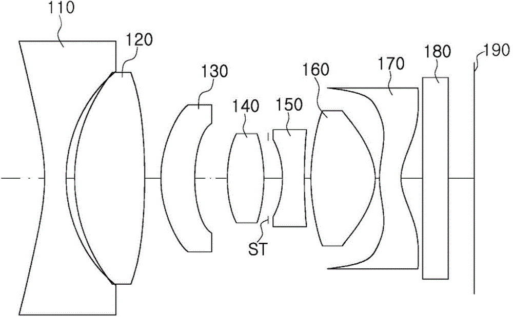
[0027] In the lens structure diagram below, the thickness, size and shape of the lens have been slightly exaggerated for ease of explanation. Specifically, the spherical or aspherical shapes shown in the lens configuration diagrams are merely examples. That is, the spherical or aspherical surfaces are not limited to having the illustrated...


PUM


Abstract

An optical system includes a first lens having negative refractive power and having two concave surfaces, a second lens having positive refractive power, a third lens having refractive power, a fourth lens having refractive power, a fifth lens having refractive power, a sixth lens having refractive power, and a seventh lens having refractive power. The first to seventh lenses are sequentially disposed from an object side. Whereby an aberration improvement effect may be increased and high resolution and a wide angle may be implemented.

Description

[0001] This application claims priority and benefit from Korean Patent Application No. 10-2014-0139756 filed with the Korean Intellectual Property Office on October 16, 2014, the disclosure of which is hereby incorporated by reference. technical field [0002] The present disclosure relates to an optical system. Background technique [0003] Recently, mobile communication terminals have been provided with camera modules so that video calls can be made and still images and moving images can be captured. Furthermore, as the functions of cameras included in mobile communication terminals have gradually increased, the cameras of mobile communication terminals are required to have a high level of resolution and a high level of performance. [0004] However, according to the tendency of mobile communication terminals to be gradually miniaturized and lightweight, there are limitations in realizing a camera module having a high level of resolution and a high level of performance. ...

Claims


Application Information

Patent Timeline
Patent Type & Authority Applications(China)
IPC IPC(8): G02B13/00G02B13/18
CPCG02B13/0045G02B13/04G02B9/64G02B13/18G02B1/041G03B9/02G03B30/00
Inventor 孙住和
Owner SAMSUNG ELECTRO MECHANICS CO LTD
Why Eureka
Try Eureka