
Method and device for algining a lens with an optical system

Inactive Publication Date: 2012-05-10
AO ETHER
View PDF9 Cites 184 Cited by
  • Summary
  • Abstract
  • Description
  • Claims
  • Application Information

AI Technical Summary

Benefits of technology

[0032]the first and second precise measurement locations are situated at the middle of the top and bottom of the image, the first precise positioning axis being the vertical axis of the image and the first and second Sagittal and Tangential Modulation Transfer Functions being Top and Bottom Sagittal and Tangential Modulation Transfer Functions; an

Problems solved by technology

Making such alignments is very time consuming.

Method used


Image

  • Method and device for algining a lens with an optical system
  • Method and device for algining a lens with an optical system
  • Method and device for algining a lens with an optical system

Examples


Embodiment Construction

[0101]Because it is not economical to correct individually the centering of each lens of a module having more than two lenses, the present invention relates in particular to modules designed such that the lens on top of the lens stack concentrates most of the convergence of the module, and the remaining lenses have a low convergence, and are just intended to correct aberrations without modifying significantly the convergence.

[0102]With such modules, only one precise alignment is required, for the top lens having the highest convergence.

[0103]In what follows, the lens on top of the stack is referred to as the top lens, and the others lenses are referred to as the fixed stack.

[0104]The present invention relates to the method to perform a precise and fast alignment of the top lens with respect to the optical axis of the fixed stack. The optical axis of the stack is practically defined as the optical axis of one of the lenses in the stack, for example the bottom lens.

[0105]The alignment...


PUM


Abstract

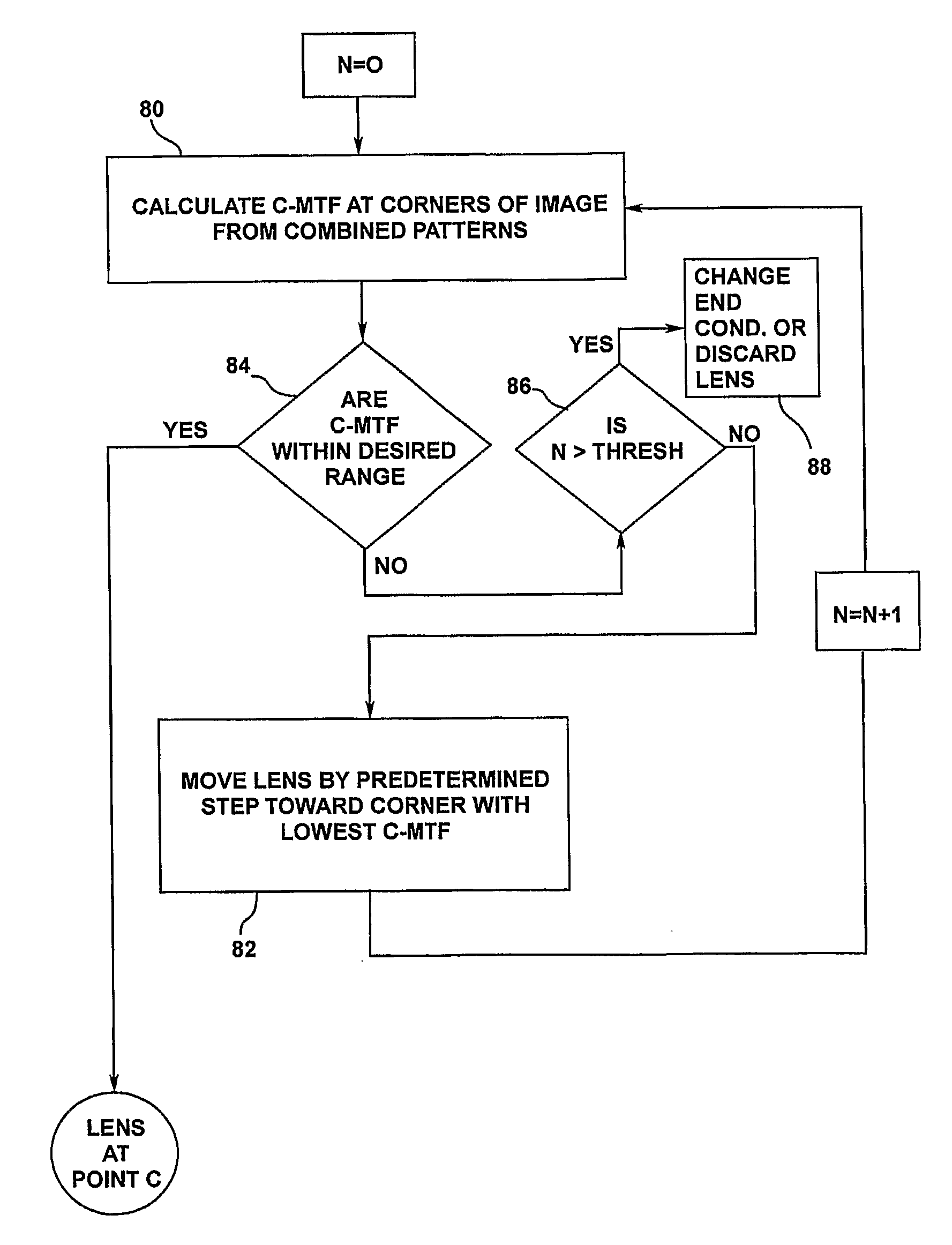
The invention comprises a process for pre-aligning a lens with an optical system, the process comprising: providing a lens and an optical system having an optical axis, wherein the lens is apt to be aligned with the optical system to form on an image plane an image of a source object, the image having top, bottom, left and right edges; coarsely positioning the lens with respect to the optical system; and in a plane normal to the optical axis of the optical system, correcting the position of the lens until the values of four Combination Modulation Transfer Functions (C-MTF) are in predetermined ranges, the C-MTF being calculated at four coarse measurement locations situated close to the edges of the image along two coarse positioning axes crossing the center of the image, each for a combination pattern comprising a combination of a Sagittal pattern and a Tangential pattern.

Description

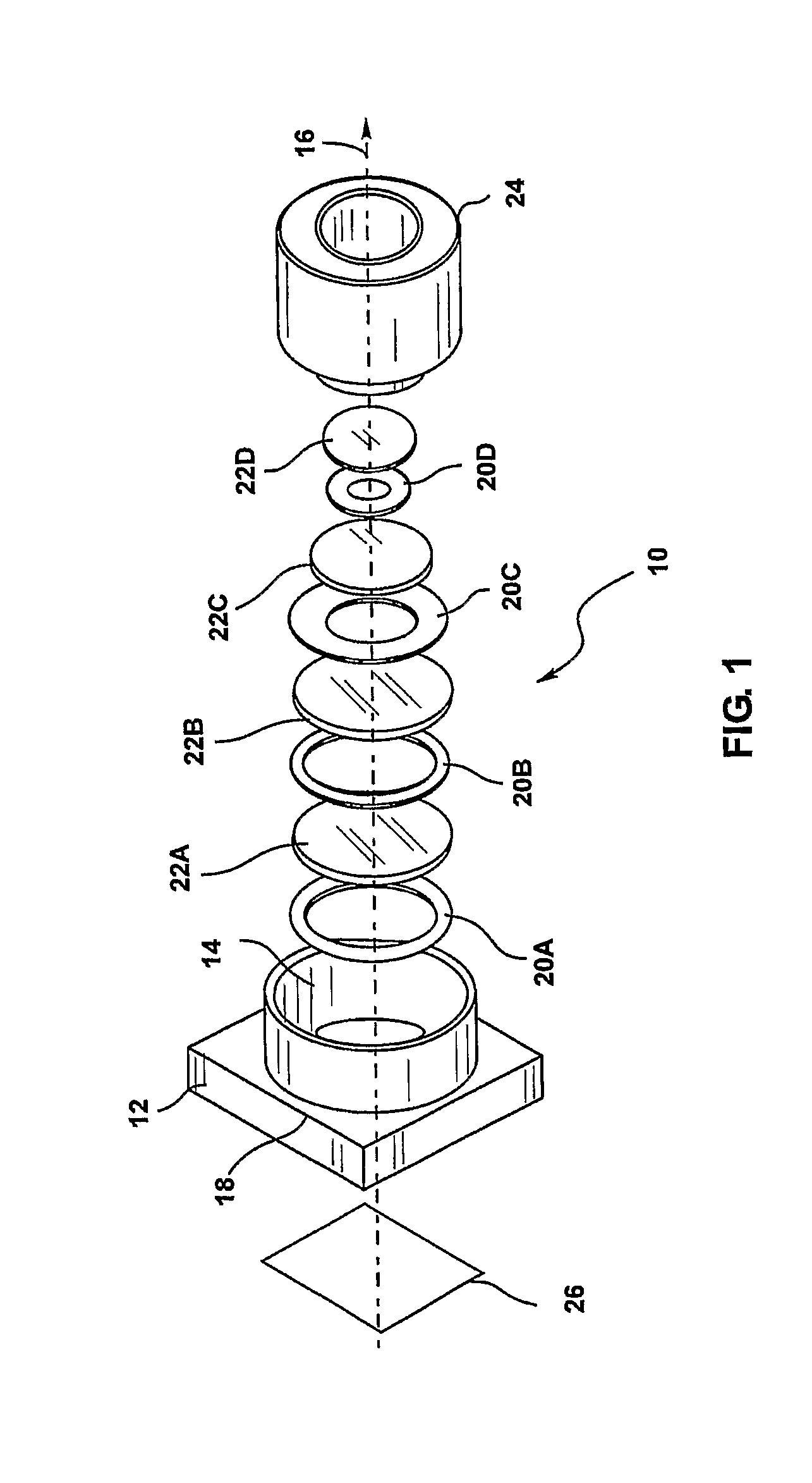
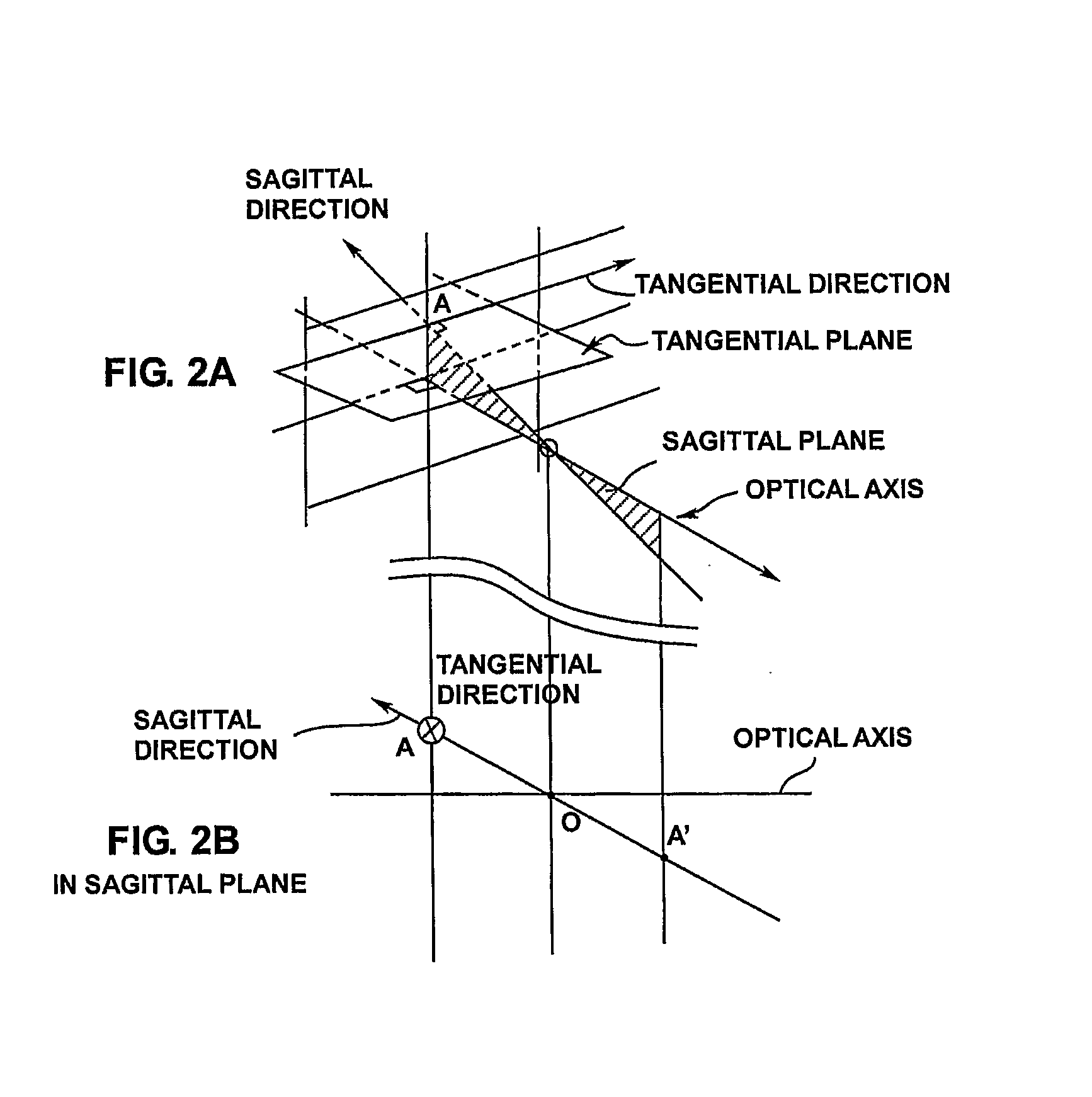
BACKGROUND OF THE INVENTION[0001]The invention relates to the manufacturing of multi lenses optical modules, such as, but not limited to, the optical modules used in the camera for mobile phones.[0002]The invention relates in particular to a method and device for aligning a lens with an optical system, the optical system comprising for example one lens or more. The invention relates more particularly to a method and device for implementing a fast coarse pre-alignment of the lens with the optical system. The coarse pre-alignment allows to subsequently rapidly conduct a precise alignment of the lens with the optical system.[0003]As a preamble, it is to be noted that the definition of the terms “focal distance”, “hyperfocal distance”, “convergence”, “optical axis”, “sagittal”, “tangential”, “MTF or Modulation Transfer Function”, “optical axis”, “spatial frequency”, “optical center” can be found in:[0004]Warren J. Smith. Modern Optical Engineering. McGraw-Hill.[0005]FIG. 1 shows an elev...

Claims


Application Information

Patent Timeline
IPC IPC(8): G01M11/02
CPCG01M11/0221G02B27/62G02B13/0015G02B7/023
Inventor MIAHCZYLOWICZ-WOLSKI, CYRILLUSINCHI, JEAN-PIERRE
Owner AO ETHER
Learn More