Total refraction optical system for collimation of led light source

A technology of LED light source and optical system, which is applied in the field of total refraction collimation optical system, can solve the problems of not using full refraction LED light source divergence angle compression optical system, etc., and achieve the effect of saving cost and reducing linearity

Active Publication Date: 2021-02-23
SHANDONG LASER TECH
View PDF5 Cites 0 Cited by
  • Summary
  • Abstract
  • Description
  • Claims
  • Application Information

AI Technical Summary

Problems solved by technology

[0004] So far, literature search has found that there is no optical system that uses total refraction to compress the divergence angle of LED light sources.

Method used


Image

  • Total refraction optical system for collimation of led light source
  • Total refraction optical system for collimation of led light source
  • Total refraction optical system for collimation of led light source

Examples


Embodiment 1

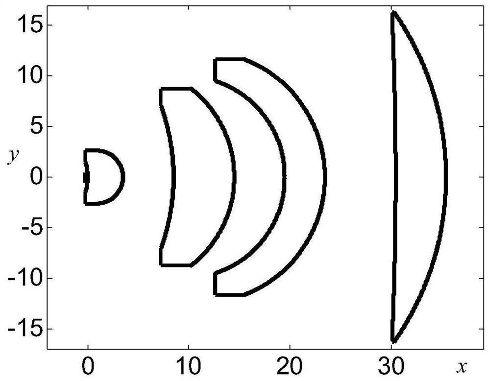
[0031] Such as figure 1 As shown, the specific design parameters of the total refraction optical system used for LED light source collimation are shown in the table below.

[0032]

[0033] The aspheric coefficient of the first aspherical surface of the first lens is as follows:

[0034] marked surface a 2

a 4

a 6

a 8

11 The first aspherical surface of the first lens -20.0 -0.05 -0.0004 -0.000005

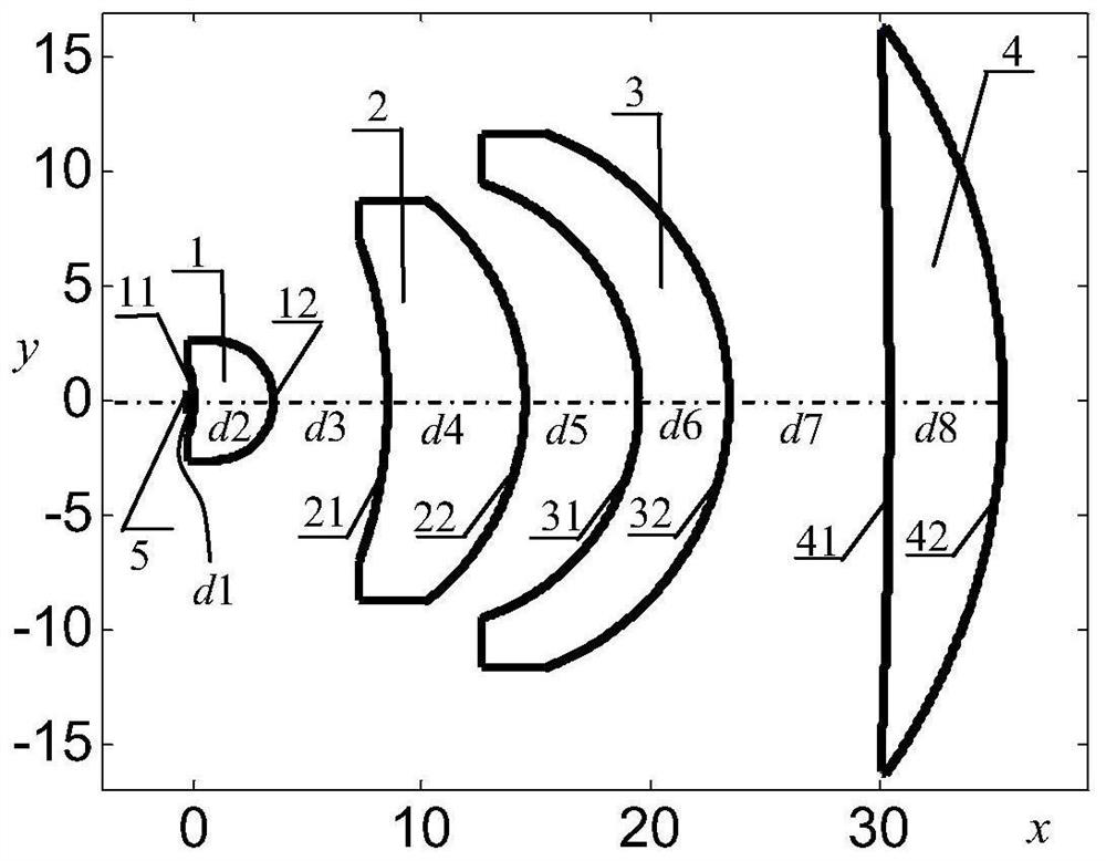
[0035] Such as image 3 As shown, the center of the 1mm×1mm LED light source 5 is located on the optical axis, and the distance between the center of the light source and the apex of the first aspheric surface 11 of the first lens is d 1 =0.3mm, the distance d from the apex of the front surface of the first lens 1 to the apex of the rear surface 2 =3.50mm; the distance d from the apex of the rear surface of the first lens 1 to the apex of the front surface of the second lens 2 3 =5.0mm, the distance d from the apex of the front surfac...


PUM

PropertyMeasurementUnit
lengthaaaaaaaaaa
refractive indexaaaaaaaaaa

Abstract

The invention relates to a total refraction collimating optical system used for collimating LED light sources, and belongs to the technical field of light emitting diode packaging and application. The total refraction collimating optical system includes a first lens, a second lens, a third lens and a fourth lens in sequence from the light source to the beam output side. The first lens is a high-order aspheric meniscus lens, including a first aspheric surface and a second spherical surface; the second lens is a spherical meniscus spherical lens, including a first spherical surface and a second spherical surface; The four lenses are also spherical meniscus spherical lenses, respectively including the first spherical surface and the second spherical surface of the third lens, and the first spherical surface and the second spherical surface of the fourth lens. All four lenses are made of crown glass with a refractive index of 1.52054. Relying on this system, the divergence angle of the LED can be compressed from ±85° to ±4.4°, and the light energy utilization rate can reach 100% within ±4.4°.

Description

technical field [0001] The invention relates to a total refraction collimating optical system for LED light source collimation, the purpose of which is to pass through the total refraction collimating optical system for the light between ±85° emitted by the 1mm×1mm LED light source without energy loss (excluding Under the conditions of Fresnel loss and material absorption), the maximum half-field angle of outgoing light is compressed to within ±4.4°, which belongs to the technical field of light-emitting diode packaging and application. Background technique [0002] The LED light source is a Lambertian illuminant. The divergence angle of the outgoing beam is between ±90°, and the light intensity distribution is uneven. If the divergence angle is not compressed and converged, it is difficult to meet the long-distance and high-brightness requirements required for lighting. Therefore, through the secondary optical design of the LED package, the divergence angle is compressed wi...

Claims


Application Information

Patent Timeline
Patent Type & Authority Patents(China)
IPC IPC(8): G02B27/30
CPCG02B27/30
Inventor 秦华颜景川
Owner SHANDONG LASER TECH
Why Eureka
Try Eureka