Optical Collimation System

An optical collimation and aperture technology, applied in the field of optical measurement, can solve the problems of small measurement field of view, long time-consuming, difficult collimation, etc., and achieve the effect of ensuring the coaxial light, intuitive real-time monitoring, and improving stability

Active Publication Date: 2022-03-04
LASER FUSION RES CENT CHINA ACAD OF ENG PHYSICS
View PDF22 Cites 0 Cited by
  • Summary
  • Abstract
  • Description
  • Claims
  • Application Information

AI Technical Summary

Problems solved by technology

[0002] A collimator is a precise angle measuring instrument. In the field of optical alignment and measurement technology, high-precision optical alignment measurement instruments are widely used, such as: autocollimator, internal focusing telescope, focal length meter, interferometer , Hartmann sensors, etc. The measurement field of view of these collimators is generally relatively small, and collimation is usually required before measurement. Because of its small field of view, it is difficult to collimate and takes a long time. Therefore, for As far as optical collimators are concerned, how to achieve rapid and rough alignment before measurement (that is, adjusting the collimation measuring instrument and the target to be measured to be basically coaxial) has always been a problem that hinders the improvement of measurement efficiency

Method used


Image

  • Optical Collimation System
  • Optical Collimation System
  • Optical Collimation System

Examples


Embodiment Construction

[0018] The present invention will be further described below with reference to the embodiments and the accompanying drawings.

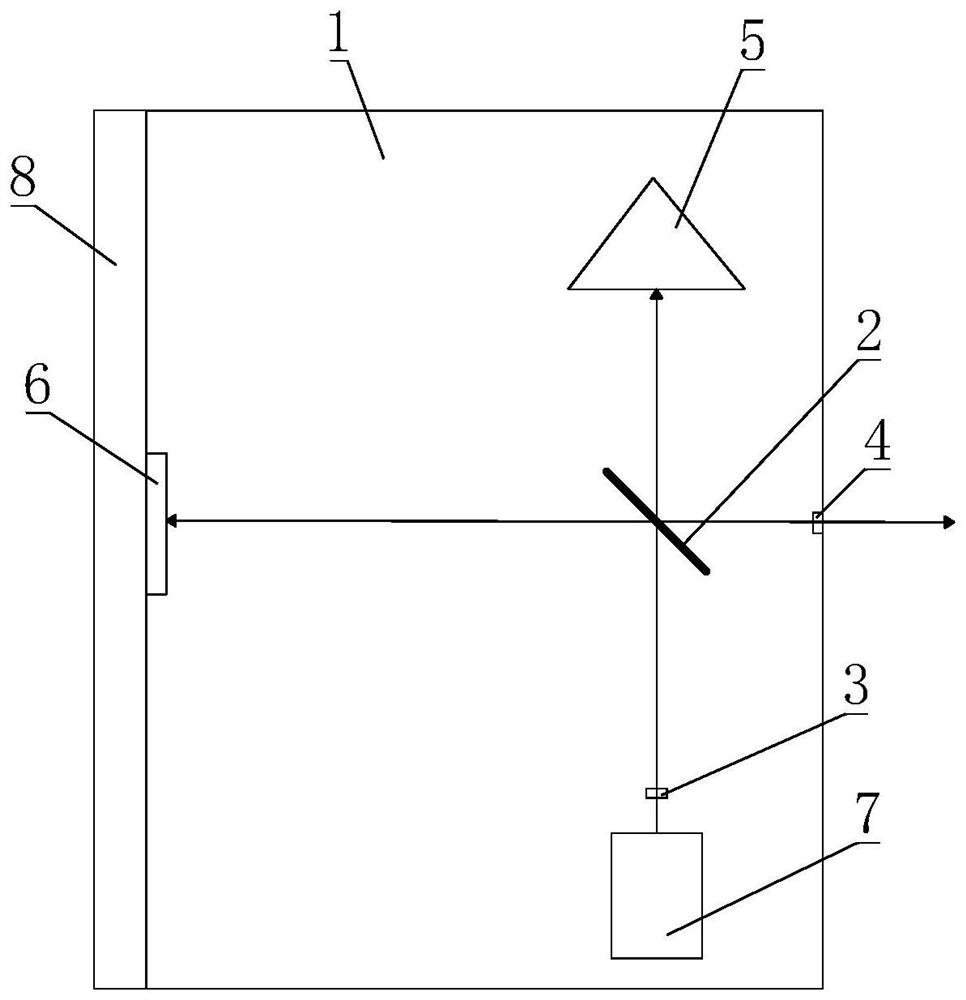
[0019] like figure 1 As shown, an optical collimation system, its structure includes a base 1 in the shape of a cuboid, a beam splitter 2 is arranged on the base 1, and a first aperture 3, a second aperture 4, a corner cone are arranged around the beam splitter 2 5 and the reflector 6, the reflector 6, the beam splitter 2 and the second diaphragm 4 are arranged in turn in the horizontal direction, the pyramid 5, the beam splitter 2 and the first diaphragm 3 are arranged in sequence along the vertical direction, and the base 1 is installed with visible light The generator 7 is used to emit visible light. In the present embodiment, the visible light generator 7 preferably uses a helium-neon laser. A reference block 8 is detachably installed on one side, the reflector 6 is a single-sided aluminized film reflector, the two sides are basically parallel, a...


PUM


Abstract

The invention discloses an optical collimation system, which comprises a base, on which a beam splitter is arranged, and a first aperture, a second aperture, a pyramid and a reflector arranged in sequence along the circumference of the beam splitter, wherein the reflector The mirror, the beam splitter and the second aperture are on the same line, the pyramid, the beam splitter and the first aperture are on the same line, and the base is equipped with a visible light generator, which is located on the side of the first aperture away from the beam splitter, so The base is detachably mounted with a reference block on the side close to the reflector. The beneficial effect of the invention is that the coaxial alignment between the axis of the measuring instrument and the normal line of the element to be measured, and the parallel alignment between elements can be realized, and the practicability and versatility are extremely high.

Description

technical field [0001] The invention belongs to the technical field of optical measurement, and in particular relates to an optical collimation system. Background technique [0002] A collimator is a precise angle measuring instrument. In the field of optical alignment and measurement technology, high-precision optical alignment measuring instruments are widely used, such as: autocollimators, internal focusing telescopes, focal length meters, interferometers , Hartmann sensor, etc. The measurement field of these collimators is generally relatively small, and usually needs to be collimated before measurement. Because of its small field of view, the collimation is difficult and time-consuming. Therefore, for As far as optical collimators are concerned, how to achieve rapid and rough alignment before measurement (that is, to adjust the collimation measurement instrument and the target to be measured to be substantially coaxial) has always been a problem that hinders the improve...

Claims


Application Information

Patent Timeline
Patent Type & Authority Patents(China)
IPC IPC(8): G01C15/00
CPCG01C15/002
Inventor 独伟锋叶朗裴国庆李珂徐旭全旭松
Owner LASER FUSION RES CENT CHINA ACAD OF ENG PHYSICS
Why Eureka
Try Eureka