light emitting device
A technology of light-emitting devices and lasers, applied in lighting devices, optics, light sources, etc., can solve the problems of intensity distribution changes, displacement of the positional relationship between light sources and lens elements, etc., and achieve the effect of not easy to change
- Summary
- Abstract
- Description
- Claims
- Application Information
AI Technical Summary
Problems solved by technology
Method used
Image
Examples
Embodiment approach 1
[0033] [Light-emitting device according to Embodiment 1]
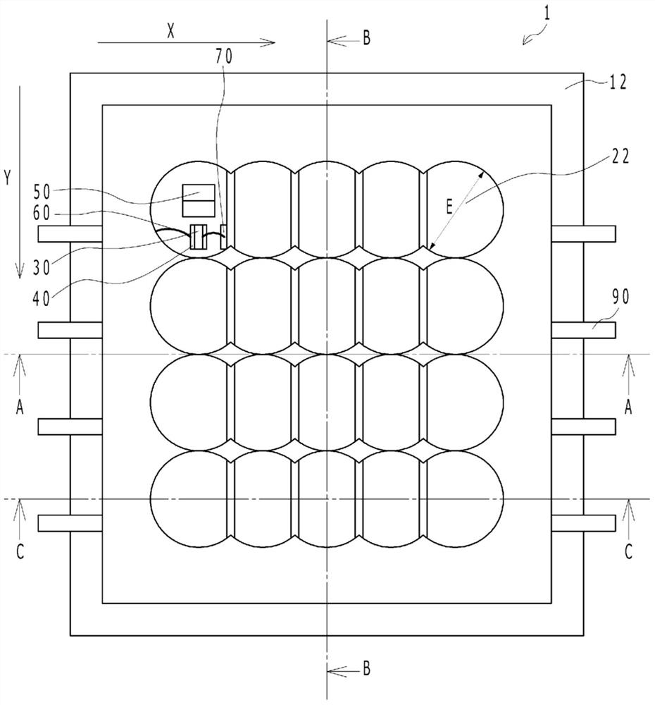
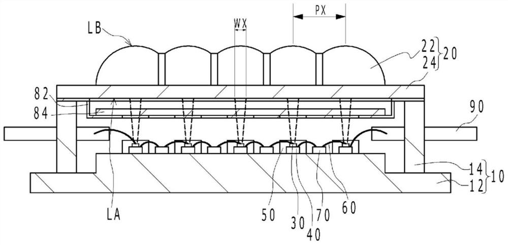
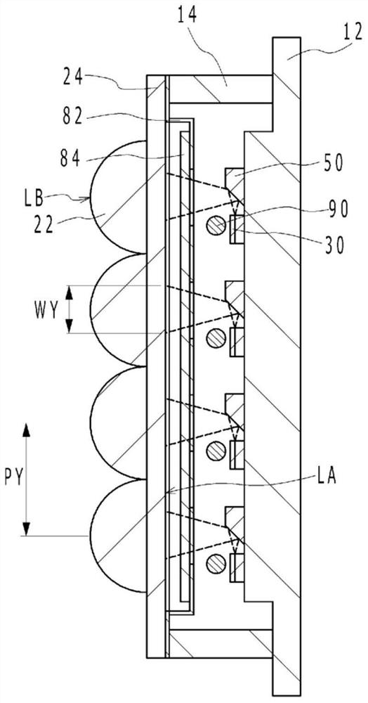
[0034] Figure 1A It is a schematic plan view of the light emitting device according to the first embodiment. in addition, Figure 1B yes Figure 1A A-A sectional view in, Figure 1C yes Figure 1A The B-B sectional view in, Figure 1D yes Figure 1A C-C sectional view in . exist Figure 1A In FIG. 2 , the semiconductor laser element 30 and the like disposed below the uppermost left lens portion are shown transparently for easy understanding. Such as Figure 1A to Figure 1D As shown, the light emitting device 1 according to Embodiment 1 includes: a substrate 10; a lens array 20 having a plurality of lens portions 22 in a matrix; and a plurality of semiconductor laser elements 30 arranged on the substrate 10, and a plurality of semiconductor laser elements. The element 30 emits laser light respectively, and each laser light has a beam shape with a wider width in the column direction than in the row direction on eac...
Embodiment approach 2
[0068] [Light-emitting device 2 according to Embodiment 2]
[0069] Figure 6A is a schematic plan view of a light emitting device according to Embodiment 2, Figure 6B yes Figure 6A M-M sectional view in, Figure 6C yes Figure 6A The N-N section view in, Figure 6D yes Figure 6A The O-O section view in . exist Figure 6A In FIG. 2 , the semiconductor laser element 30 and the like disposed below the uppermost left lens portion are shown transparently for easy understanding. Such as Figure 6A to Figure 6D As shown, in the light-emitting device 2 according to Embodiment 2, the plurality of lens arrays 20A, 20B, 20C, and 20D are arranged in the column direction (Y direction in FIG. 1 ), and the plurality of lens arrays 20A, 20B, 20C, and 20D are arranged in the row direction The direction (X direction in FIG. 1 ) is different from the light-emitting device 1 according to Embodiment 1 in that it has a plurality of lens portions 22 . Even according to Embodiment 2, si...
Embodiment approach 3
[0070] [Light-emitting device 3 according to Embodiment 3]
[0071] Figure 7 A schematic plan view of a light emitting device 3 according to Embodiment 3 is shown. Figure 7 The outer edge of the concave portion 82b is indicated by a dotted line. In addition, in Figure 7 In , hatching is applied to the area where the lens array 20 is fixed to the sealing member 80 by the adhesive. Such as Figure 7 As shown, in the light emitting device 3 , the lens array 20 includes the connecting portion 24 connecting the lens portions 22 to each other, and is fixed to the sealing member 80 at the connecting portion 24 with an adhesive. The sealing member 80 has a concave portion 82 b that is recessed toward a region of the base body 10 on which the plurality of semiconductor laser elements 30 are placed. The lens array 20 has a through-hole F inside the concave portion 82b in plan view, and is fixed to the sealing member 80 with an adhesive outside the concave portion 82b.
[0072] ...
PUM
 Abstract
Description
Claims
Application Information
 - R&D
- Intellectual Property
- Life Sciences
- Materials
- Tech Scout
- Unparalleled Data Quality
- Higher Quality Content
- 60% Fewer Hallucinations
Browse by: Latest US Patents, China's latest patents, Technical Efficacy Thesaurus, Application Domain, Technology Topic, Popular Technical Reports.
© 2025 PatSnap. All rights reserved.Legal|Privacy policy|Modern Slavery Act Transparency Statement|Sitemap|About US| Contact US: help@patsnap.com


