Transmissions for Motor Vehicles

A technology for transmissions and motor vehicles, which is applied in the direction of vehicle gearboxes, transmissions, mechanical equipment, etc. It can solve the problems of high component load of clutches and short residence time of sub-transmissions, and achieve the effect of reducing the number

Active Publication Date: 2019-03-12
AUDI AG
View PDF1 Cites 0 Cited by
  • Summary
  • Abstract
  • Description
  • Claims
  • Application Information

AI Technical Summary

Problems solved by technology

In this shift sequence, the dwell time in the subtransmission of the second gear is very short, resulting in high component loads on the clutches

Method used


Image

  • Transmissions for Motor Vehicles
  • Transmissions for Motor Vehicles
  • Transmissions for Motor Vehicles

Examples


Embodiment Construction

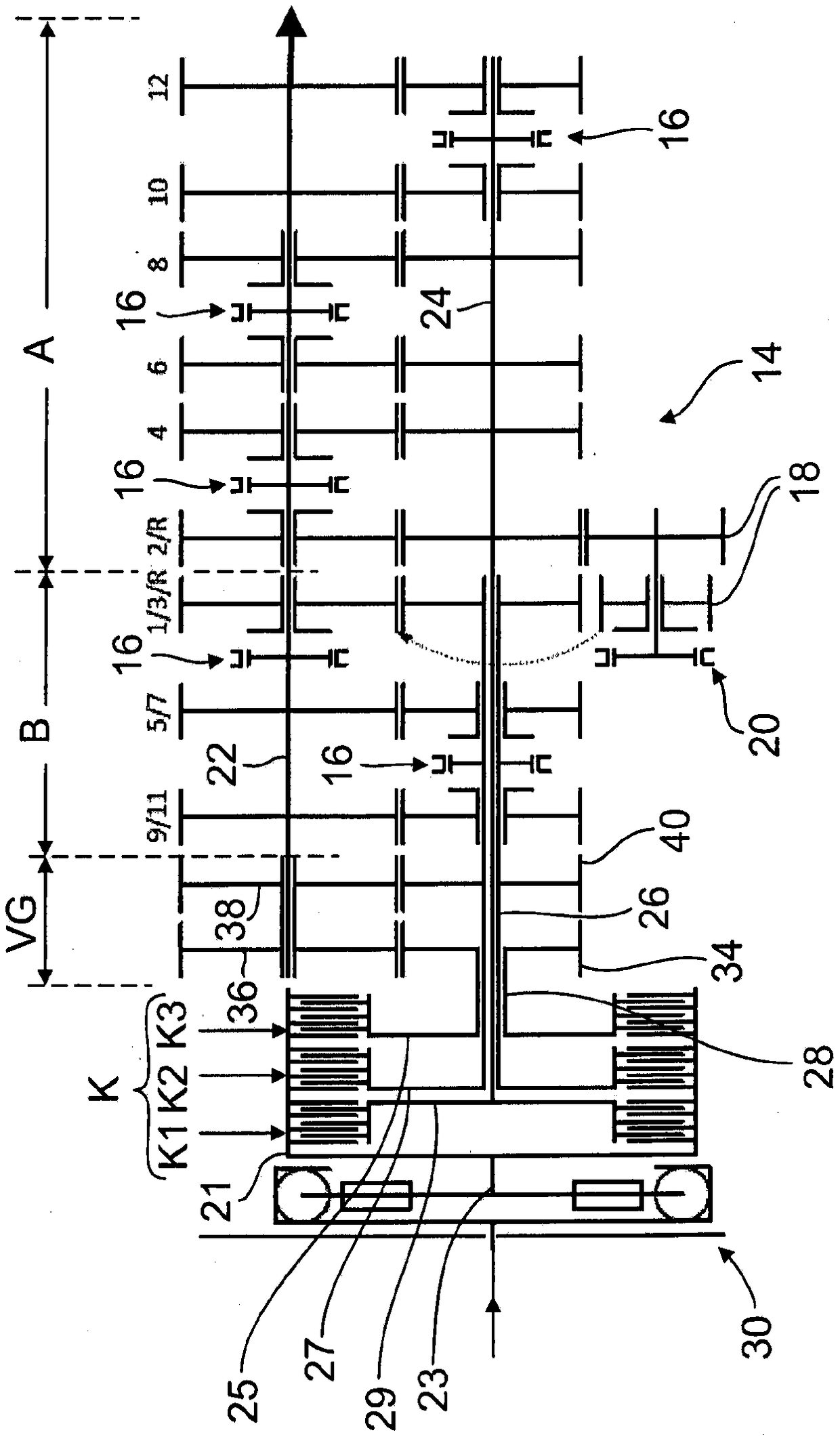
[0031] exist figure 1 shows a block diagram of a transmission 14 for a motor vehicle, which in the exemplary embodiment has twelve forward gears 1 to 12 and a total of three reverse gears R, which are formed by gear sets meshing with each other, wherein the gear sets can The shifting takes place in a manner known per se via shifting or synchronous clutches (identified collectively with 16 ) on the floating gear.

[0032]The gear set with fixed gears and switchable floating gears is divided into two sub-transmissions A and B, where sub-transmission B corresponds to the odd numbered forward gears (from left to right in the drawing) 9 / 11, 5 / 7 and 1 / 3 , and the even-numbered gears 2, 4, 6, 8, 10, and 12 can be switched through corresponding multiple gear sets via the sub-transmission A.

[0033] anyway in figure 1 The clutches K1, K2 and K3 can be used to switch the three reverse gears R. The reverse gear R, which differs in transmission ratio, can be shifted by means of the ge...


PUM


Abstract

The invention relates to a transmission for a motor vehicle with a switchable gear set, which is assigned to a first sub-transmission and a second sub-transmission, wherein the sub-transmissions each have an input shaft and a common output shaft, And the input shafts can be activated alternately via the powershift clutches, respectively. The transmission, which is advantageous in terms of construction and function, is realized in that one of the subtransmissions (B) is equipped with an auxiliary unit (VG) which causes a change in the gear ratio, which can be alternately driven by the third powershift clutch (K3 ). ) on.

Description

technical field [0001] The invention relates to a transmission for a motor vehicle. Background technique [0002] Such transmissions are known as so-called dual-clutch transmissions and are commonly used in motor vehicles. In addition to good efficiency, this transmission also has the advantage that it can be shifted in particular automatically without interruption of tractive force, wherein a transmission gear can be preselected in an inactive sub-transmission, and then the Transmission gears are activated by shifting the powershift clutch. In the possible use case, it is expedient to provide the odd gears (1, 3, 5, etc.) in one of the sub-transmissions and the even gears (2, 5, etc.) in the other sub-transmission by means of the corresponding gearset. 4, 6, etc.), the gear set is drivingly connected to the respective input shaft or output shaft, for example, via a synchromesh gear. [0003] As mentioned above, each sub-transmission has a power shift clutch respectively....

Claims


Application Information

Patent Timeline
Patent Type & Authority Patents(China)
IPC IPC(8): F16H3/00F16H3/089
CPCF16H3/006F16H3/089F16H2003/0826F16H2200/0078F16H2003/007
Inventor S·胡梅尔
Owner AUDI AG
Why Eureka
Try Eureka