Filtering and dust collection device for operating room

A vacuum device and operating room technology, which is applied in the field of medical equipment, can solve the problems of electric leakage of medical auxiliary equipment in the operating room, affecting the environmental sanitation of the operating room, and water accumulation on the ground, so as to achieve improved suction, good cleaning effect, and improved cleaning efficiency. Effect

Inactive Publication Date: 2016-12-07
江苏翊博雷明医疗科技有限公司
View PDF5 Cites 0 Cited by
  • Summary
  • Abstract
  • Description
  • Claims
  • Application Information

AI Technical Summary

Problems solved by technology

[0002] In the application of minimally invasive treatment techniques such as arthroscopy and cystoscopy, a large amount of lavage fluid is required to be flushed. Due to the existing operating room conditions, there is no corresponding auxiliary drainage facility, which will lead to a large amount of water on the ground, and then Cause ground deformation, leakage of medical auxiliary equipment in the operating room, and seriously affect the environmental sanitation of the operating room

Method used


Image

  • Filtering and dust collection device for operating room

Examples


Embodiment 1

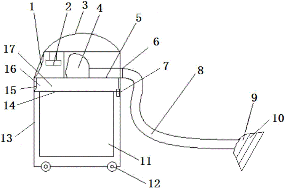
[0017] Embodiment one: if figure 1 As shown, the present invention comprises box body 13, and box body 13 top is provided with loam cake 17, and loam cake 17 interior is provided with air blower 2, and loam cake 17 side wall is provided with peep window 1, and loam cake 17 bottom is provided with solid collecting box. 16, the bottom of the solid collection box 16 is provided with a filter screen 14, the side of the solid collection box 16 is provided with a pull opening 15, the inside of the upper cover 17 is provided with a suction pipe 5, and one end of the suction pipe 5 is connected to the upper cover 17 is connected to the filter inlet 4 inside, the other end of the suction pipe 5 is connected to the external hose 8 through the nozzle 6, the other end of the hose 8 is connected to the suction hood 9, and the upper cover 17 is connected to the connecting piece 7 It is connected with the box body 13, and the inside of the box body 13 is provided with a detachable collection...

Embodiment 2

[0019] Embodiment 2: The present invention includes a box body 13, the top of the box body 13 is provided with an upper cover 17, the inside of the upper cover 17 is provided with a blower 2, the side wall of the upper cover 17 is provided with a peep window 1, and the bottom of the upper cover 17 is provided with a solid collection Box 16, the bottom of the solid collection box 16 is provided with a filter screen 14, the side of the solid collection box 16 is provided with a pull port 15, the inside of the upper cover 17 is provided with a suction pipe 5, and one end of the suction pipe 5 is connected to the upper The filter inlet 4 inside the cover 17 is connected, the other end of the suction pipe 5 is connected to the external hose 8 through the nozzle 6, the other end of the hose 8 is connected to the suction hood 9, and the upper cover 17 is connected through a connecting piece 7 is connected with the box body 13, and the inside of the box body 13 is provided with a detac...


PUM


Abstract

The invention discloses a filtering and dust collection device for an operating room. The device comprises a box, an upper cover is arranged on the top of the box, an air feeder is arranged in the upper cover, an observation window is formed in the side wall of the upper cover, a solid collection box is arranged at the bottom of the upper cover, a filter screen is disposed at the bottom of the solid collection box, a pulling opening is formed in the side face of the solid collection box, an air suction pipe is arranged in the upper cover, one end of the air suction pipe is connected with a filtering inlet in the upper cover, the other end of the air suction pipe is connected with an external hose, the other end of the hose is connected with an air suction cover, the upper cover is connected with the box through connecting elements, a detachable collection bag is arranged in the box, and four universal wheels are arranged at the bottom of the box. The device has the advantages that the structure is simple, manufacturing cost is low, use is safe and reliable, sewage and dirt on the ground surface can be absorbed, and solid and liquid can be conveniently classified.

Description

technical field [0001] The invention relates to the technical field of medical instruments, in particular to a filter and dust suction device for an operating room. Background technique [0002] In the application of minimally invasive treatment techniques such as arthroscopy and cystoscopy, a large amount of lavage fluid is required to be flushed. Due to the existing operating room conditions, there is no corresponding auxiliary drainage facility, which will lead to a large amount of water on the ground, and then It leads to deformation of the ground, leakage of medical auxiliary equipment in the operating room, and in severe cases affects the environmental sanitation of the operating room. Contents of the invention [0003] Purpose of the invention: In order to overcome the deficiencies in the prior art, the present invention provides a simple structure, low manufacturing cost, safe and reliable use, can attract sewage and dirt on the ground surface at the same time, and...

Claims


Application Information

Patent Timeline
IPC IPC(8): A47L11/30A47L11/40
CPCA47L11/30A47L11/4013A47L11/4027
Inventor 李雷
Owner 江苏翊博雷明医疗科技有限公司
Why Eureka
Try Eureka