
Discharge device of hardware punch press

A technology of discharging device and hardware, applied in the field of hardware processing, can solve the problems of low discharging efficiency and increase labor intensity, and achieve the effects of reasonable structure, reducing labor intensity and improving discharging efficiency.

Pending Publication Date: 2018-03-06
HAIYAN HONGQIANG HARDWARE MFG CO LTD
View PDF0 Cites 0 Cited by
  • Summary
  • Abstract
  • Description
  • Claims
  • Application Information

AI Technical Summary

Problems solved by technology

[0003] The purpose of the present invention is to overcome the above-mentioned deficiencies in the prior art, and provide a discharge device for a hardware punching machine, which aims to solve the need for manual auxiliary discharge of the hardware in the prior art after being processed and formed on the punch press, which improves the manual labor. strength, and the technical problem of low discharge efficiency

Method used


Image

  • Discharge device of hardware punch press
  • Discharge device of hardware punch press

Examples


Embodiment Construction

[0015] In order to make the object, technical solution and advantages of the present invention clearer, the present invention will be further described in detail below with reference to the accompanying drawings and embodiments. However, it should be understood that the specific embodiments described here are only used to explain the present invention, and are not intended to limit the scope of the present invention. Also, in the following description, descriptions of well-known structures and techniques are omitted to avoid unnecessarily obscuring the concept of the present invention.

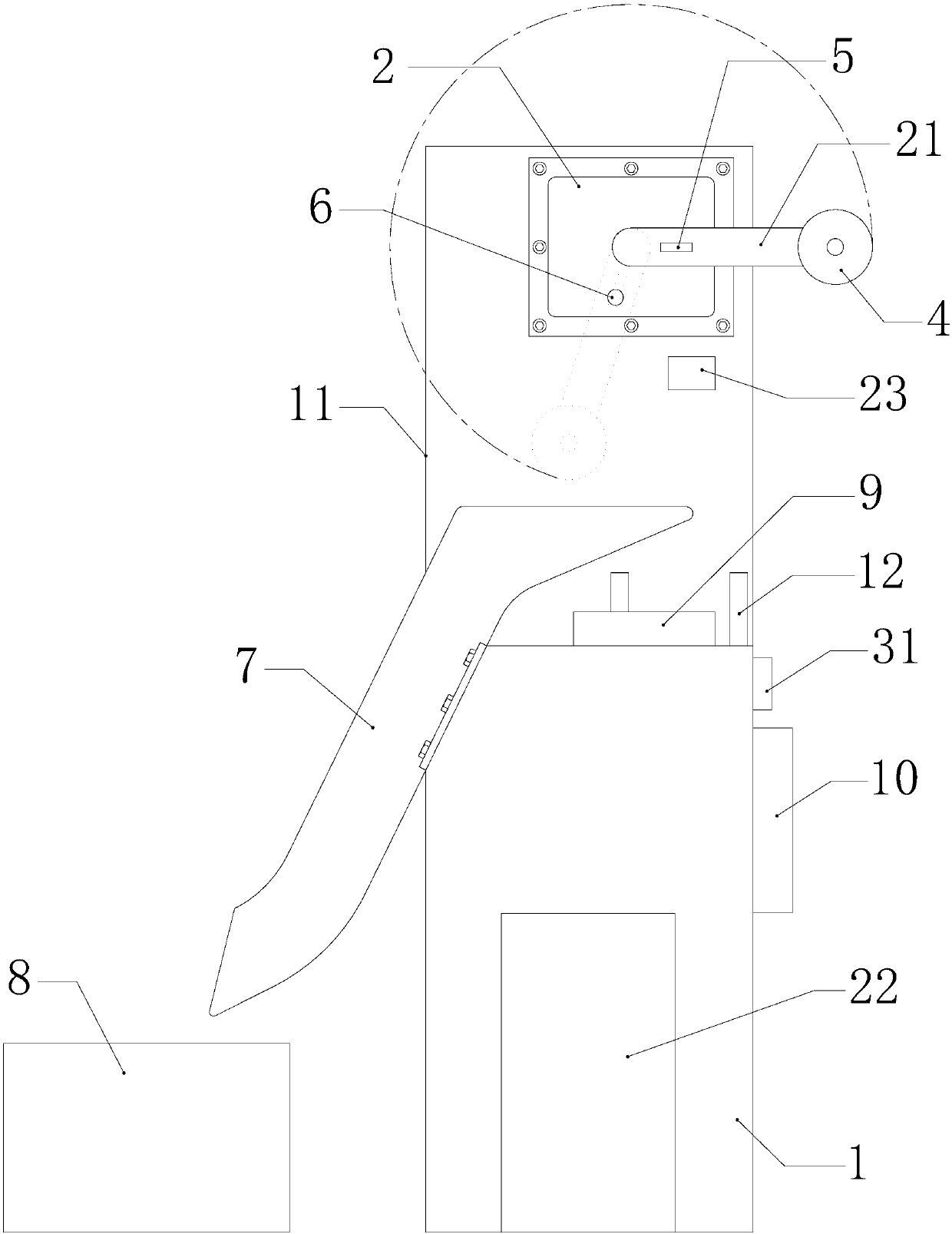
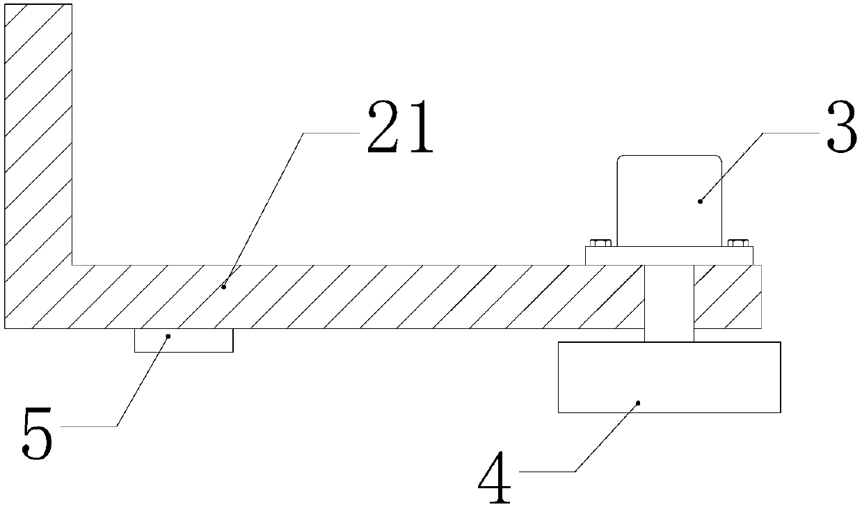
[0016] refer to figure 1 and figure 2 The embodiment of the present invention provides a discharge device for a hardware punching machine, including a box body 1, a swing cylinder 2, an electric motor 3, an electromagnet 4, a control switch 5, a discharge pipeline 7, a receiving box 8 and a control device 9 , the discharge pipeline 7 is fixedly installed on the box body 1 through fasteners,...


PUM


Abstract

The invention discloses a discharge device of a hardware punch press. The discharge device comprises a box body, an oscillating cylinder, an electric motor, an electromagnet, a control switch, a discharge pipeline, a material collecting box and a control device, wherein the discharge pipeline is fixedly mounted on the box body through a fastener; the material collecting box is arranged below a discharge opening of the discharge pipeline; the oscillating cylinder is further fixedly mounted on the box body; the electric motor is connected with a rotating shaft of the oscillating cylinder througha connecting rod; the electromagnet is mounted on an output shaft of the electric motor; the electromagnet is electrically connected with a power source through the control switch; and the control switch and the control device are in communication connection. According to the discharge device, the electromagnet is connected to the oscillating cylinder through the connecting rod, and suction, transfer and discharge of parts are achieved through swinging of the electromagnet; and besides, the electromagnet is connected with the electric motor, autorotation of the electromagnet is achieved, a plurality of parts can be sucked in one swinging cycle, labor intensity is greatly reduced, and discharge efficiency of the parts is improved.

Description

【Technical field】 [0001] The invention relates to the technical field of hardware processing, in particular to a discharge device for a hardware punching machine. 【Background technique】 [0002] Hardware refers to machine parts or components made of hardware, as well as some small hardware products. It can be used alone or as an auxiliary tool. It is widely used in various fields of life and can usually be attracted by magnetic magnets. At present, after the hardware is processed and formed on the punching machine, manual auxiliary discharge is required, which increases the labor intensity and the discharge efficiency is low. In order to solve the above problems, it is necessary to propose a discharge device for the hardware punching machine. 【Content of invention】 [0003] The purpose of the present invention is to overcome the above-mentioned deficiencies in the prior art, and provide a discharge device for a hardware punching machine, which aims to solve the need for m...

Claims


Application Information

Patent Timeline
IPC IPC(8): B21D45/02B21D43/20
Inventor 钟岳祥
Owner HAIYAN HONGQIANG HARDWARE MFG CO LTD
Learn More