Ink adsorption system and working principle thereof

An ink absorption and ink technology, which is applied in the field of ink absorption system and its working principle, can solve the problems of unsatisfactory ink absorption effect, difficulty in adjusting suction force, and prone to failure, and achieve the effects of low power, reduced noise, and reduced failure rate

Active Publication Date: 2015-11-04
GUANGDONG DONGFANG PRECISION SCI & TECH CO LTD
View PDF13 Cites 0 Cited by
  • Summary
  • Abstract
  • Description
  • Claims
  • Application Information

AI Technical Summary

Problems solved by technology

[0002] All ceramic inkjet printers have an adsorption system. The adsorption system is composed of a vacuum pump and an exhaust fan. The function of the vacuum pump and the exhaust fan is to generate positive and negative pressure in the adsorption system. The function is to discharge ink, and the existing adsorption system has the following disadvantages due to the use of a vacuum pump and a blower: the blower of the vacuum pump adopts a vacuuming method to realize positive pressure and negative pressure, and its pressure is only one atmospheric pressure, while The actual pressure generated is often less than the actual working output pressure of the vacuum pump and exhaust fan. Due to the large volume of ceramic inkjet printers, the power of the vacuum pump and exhaust fan required must be increased, and the energy loss is large, and the effect of ink absorption is not ideal. , and the suction adjustment is quite difficult, ceramic inkjet printers are often prone to failure during use

Method used


Image

  • Ink adsorption system and working principle thereof

Examples


Embodiment Construction

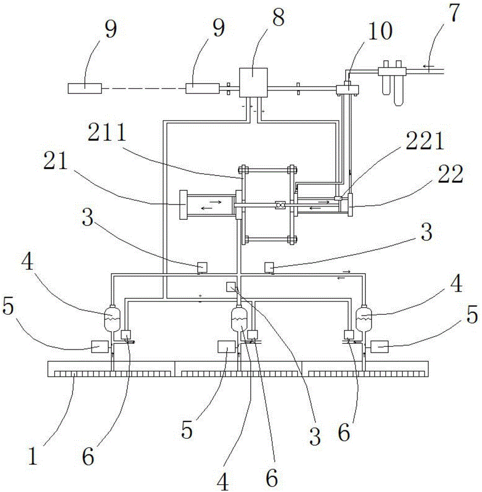
[0012] The specific implementation manners of the present invention will be described in further detail below in conjunction with the accompanying drawings.

[0013] See attached figure 1 , the ink adsorption system of the present invention comprises ink cartridge 1, ink throttle valve 3, filter tank 4, one-way throttle valve 5, air inlet 7, PLC control module 8, enters brick to radio eye 9, one-way throttle valve 5 is installed between the ink cartridge 1 and the filter tank 4. There is a T-shaped ink discharge branch between the ink cartridge 1 and the filter tank 4. The upper part of the filter tank 4 is connected to one end of the ink throttle valve 3 through a gas pipe. The other end of flow valve 3 is connected with a positive and negative pressure cylinder 21, the connecting rod of the positive and negative pressure cylinder 21 is connected with the connecting rod of a push-pull cylinder 22, and the positive and negative pressure cylinder 21 and the push-pull cylinder 2...


PUM


Abstract

The invention discloses an ink adsorption system and a working principle thereof. According to the working principle of the ink adsorption system, external gas flows in from an air inlet, and then is led to a solenoid valve; when a brick triggers a brick feeding through-beam electric eye, signals are sent to a PLC control module for calculating stroke; the solenoid valve is electrified, so that the gas can be outputted along one gas path, and therefore, a push-pull air cylinder pushes forward a positive and negative-pressure air cylinder; the push-pull air cylinder and the positive and negative-pressure air cylinder move synchronously; the positive and negative-pressure air cylinder generates negative pressure, so that ink can be absorbed into filter tanks from a nozzle installing plate; the push-pull air cylinder is pushed to a vertex, triggering signals are transmitted to the PLC control module; electric throttle valves are opened; the solenoid valve makes the gas outputted from the other gas path, so that the push-pull air cylinder is pulled backwards; and the positive and negative-pressure air cylinder generates positive pressure, and therefore, waste ink can be discharged from the filter tanks.

Description

technical field [0001] The invention relates to the field of ceramics, in particular to an ink absorption system and its working principle. Background technique [0002] All ceramic inkjet printers have an adsorption system. The adsorption system is composed of a vacuum pump and an exhaust fan. The function of the vacuum pump and the exhaust fan is to generate positive and negative pressure in the adsorption system. The function is to discharge ink, and the existing adsorption system has the following disadvantages due to the use of a vacuum pump and a blower: the blower of the vacuum pump adopts a vacuuming method to realize positive pressure and negative pressure, and its pressure is only one atmospheric pressure, while The actual pressure generated is often less than the actual working output pressure of the vacuum pump and exhaust fan. Due to the large volume of ceramic inkjet printers, the power of the vacuum pump and exhaust fan required must be increased, and the ener...

Claims


Application Information

Patent Timeline
IPC IPC(8): B41J2/175
Inventor 何小燕
Owner GUANGDONG DONGFANG PRECISION SCI & TECH CO LTD
Why Eureka
Try Eureka