Angle adjustment mechanism, ultrasonic imaging system thereof and trolley

A technology of angle adjustment and adjustment parts, applied in ultrasonic/sonic/infrasonic diagnosis, sonic diagnosis, infrasonic diagnosis, etc., can solve the problem of inability of medical staff to adjust the position, leakage of couplant heater, inability to reverse or angle adjustment, etc.

Active Publication Date: 2016-12-07
SHENZHEN MINDRAY BIO MEDICAL ELECTRONICS CO LTD
View PDF6 Cites 2 Cited by
  • Summary
  • Abstract
  • Description
  • Claims
  • Application Information

AI Technical Summary

Problems solved by technology

[0003] The existing designs of couplant heaters for ultrasound imaging systems are divided into two categories: one is fixed couplant heaters, and the couplant heaters are fixed on the ultrasound imaging system, and the position cannot be adjusted according to the usage habits of medical staff
The other type is desktop-placed couplant heaters, which are mostly placed upright and cannot be turned upside down or angled.
[0004] For the first type of implementation, because the heater is fixed inside the instrument, it cannot meet the requirements of different operations, diagnosis, and treatment habits, and there are problems such as leakage of fluid inside the couplant heater, dirt and inconvenient cleaning
For the second type of implementation, there is also the problem that it cannot meet the requirements of different operations, diagnosis, and treatment habits, and at the same time, it is easy to knock over when using it.

Method used


Image

  • Angle adjustment mechanism, ultrasonic imaging system thereof and trolley
  • Angle adjustment mechanism, ultrasonic imaging system thereof and trolley
  • Angle adjustment mechanism, ultrasonic imaging system thereof and trolley

Examples


Embodiment Construction

[0030] The present invention will be further described in detail below through specific embodiments in conjunction with the accompanying drawings.

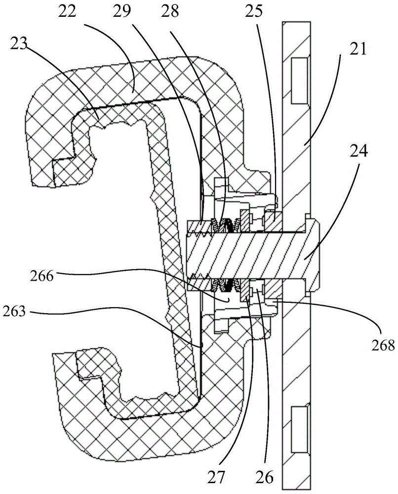
[0031] An angle adjustment mechanism, capable of cooperating with a couplant heater, includes an integrally connected shaft core, a fixing bracket, an adjustment piece and an elastic piece. The shaft core and the fixed bracket form a rotating pair, so that the shaft core can rotate relative to the fixed bracket. The adjustment part can rotate synchronously with the shaft core, so that the adjustment part and the fixed bracket can rotate relatively. The adjusting part is frictionally fitted with the fixing bracket, and the rotation damping between the two can be provided by the elastic part, and the adjusting part is pressed against the fixing bracket by the elastic force of the elastic part. One of the fixed bracket and the adjusting member is provided with a gear block, the other of the fixed bracket and the adjusting member is ...


PUM


Abstract

The invention discloses an angle adjustment mechanism and an ultrasonic imaging system. The angle adjustment mechanism can be coupled with a coupling agent heater and comprises a mandrel, a fixing support, an adjusting part and an elastic part which are connected integrally, wherein the mandrel and the fixing support form a rotating pair, the adjusting part and the mandrel perform synchronous rotation, a gear block is arranged in one of the adjusting part and the fixing support, the other one of the adjusting part and the fixing support is provided with a gear adjusting face, the gear adjusting face is provided with a circle of gear grooves in a concave mode, the part, located between every two adjacent gear grooves of the gear adjusting face is a transition face, and the elastic part makes the gear block and the gear adjusting face matched in a frictional mode. The angle adjustment mechanism facilitates any coupling agent heater angle adjustment performed by a user according to different usage habits of operation, diagnosis and treatment, further can adjust the taking and putdown angle of the coupling agent heater, provides rotation damping through the elastic part, makes the coupling agent heater stably stop at different angles, accordingly facilitates free taking and putdown and is stable to take and put down.

Description

technical field [0001] The present application relates to the field of ultrasonic imaging systems, in particular to an ultrasonic imaging system provided with a couplant heater and a trolley for the ultrasonic imaging system. Background technique [0002] When medical personnel use ultrasound imaging systems, they often need to cooperate with the use of couplant heaters. Based on the needs of operation, diagnosis and treatment, especially when doing different body position examinations, the placement of the couplant heater is required to meet the needs of operation, diagnosis and treatment, which requires the placement of the couplant heater to have an angle adjustment function for convenience. Operating habits of medical staff. [0003] The existing designs of couplant heaters for ultrasound imaging systems are divided into two categories: one is fixed couplant heaters, and the couplant heaters are fixed on the ultrasound imaging system, and the position cannot be adjusted...

Claims


Application Information

Patent Timeline
Patent Type & Authority Applications(China)
IPC IPC(8): A61B8/00
Inventor 杨荣富赵彦群陈志武黄力锋
Owner SHENZHEN MINDRAY BIO MEDICAL ELECTRONICS CO LTD
Why Eureka
Try Eureka