Metal debris filtering mechanism

A technology of filtering mechanism and metal debris, which is applied in the fields of filtration and separation, fixed filter element filter, chemical instruments and methods, etc., can solve the problems of labor-intensive, reduced production efficiency, unable to achieve continuous recycling, etc., and achieves economical practicability. Strong, simple structure

Inactive Publication Date: 2016-12-07
张家港市华扬冶金机械有限公司
View PDF6 Cites 11 Cited by
  • Summary
  • Abstract
  • Description
  • Claims
  • Application Information

AI Technical Summary

Problems solved by technology

[0002] In the machining place, it is necessary to flush the workpiece and the tool with the coolant to wash away the metal debris generated during the machining process. The metal debris will be discharged through the chip discharge channel with the coolant. After cooling, the coolant is collected in the cooling water tank, pumped to the workpiece and the tool by an external water pump, and then cooled again, so as to achieve the purpose of circulating cooling. However, metal chips during processing will flow into the cooling water with the coolant. Water tank, and the current cooling water tank does not have a filter device, so it is easy to cause the water pump to block and the cooling water tank cannot achieve the effect of continuous circulation, or the cooling liquid is mixed with impurities, which will affect the machining accuracy and affect the service life of the tool. Cleaning needs to be done manually, and the filter box must be moved, and the incoming and outgoing pipelines and circuits must be disassembled during cleaning, which is not only troublesome but also time-consuming, resulting in reduced production efficiency and increased production costs. Metal shavings and coolant, which need to be removed in order not to interfere with the work process, will help keep the work area clean and increase productivity

Method used


Image

  • Metal debris filtering mechanism

Examples


Embodiment Construction

[0013] The technical solutions in the embodiments of the present invention will be clearly and completely described below in conjunction with the accompanying drawings in the embodiments of the present invention. Obviously, the described embodiments are only some of the embodiments of the present invention, not all of them. Based on The embodiments of the present invention and all other embodiments obtained by persons of ordinary skill in the art without making creative efforts belong to the protection scope of the present invention.

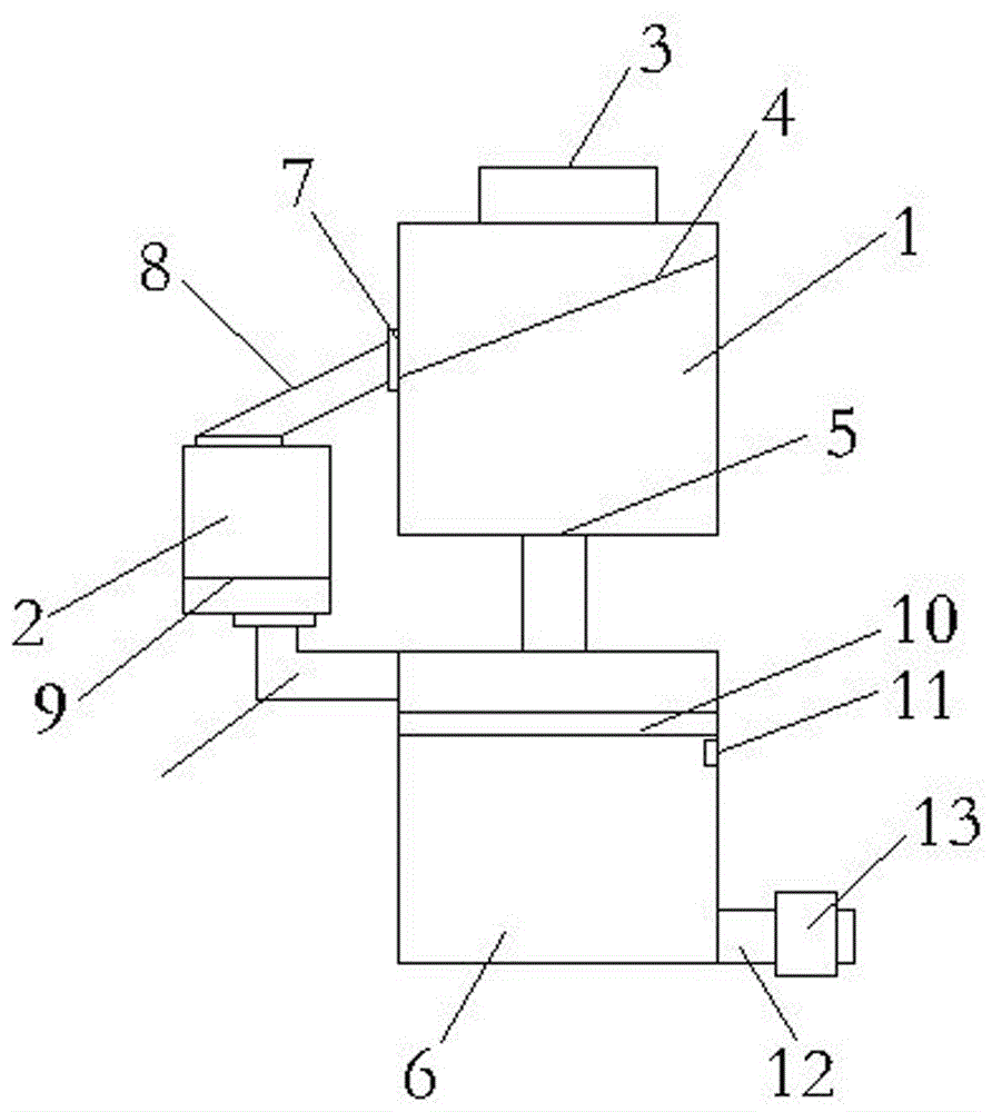
[0014] see figure 1 , a metal debris filtering mechanism, comprising a coarse filter box 1 and a debris collection box 2, the top of the coarse filter box 1 is provided with a material inlet 3, metal debris containing cooling liquid enters from the material inlet 3, the coarse The inner cavity of the filter box 1 is provided with an inclined coarse filter screen 4, which filters and retains large particles of metal debris, and the cooling liquid...


PUM


Abstract

The invention relates to a metal debris filtering mechanism. The metal debris filtering mechanism comprises a coarse filter box and a scrap collecting box, wherein a material inlet is formed in the top of the coarse filter box; an inclined coarse filter screen is arranged inside an inner cavity of the coarse filter box; a liquid outlet is formed in the bottom of the coarse filter box; a liquid collecting box is connected to the bottom of the liquid outlet through a pipe; a movable connecting device is arranged on one side of the coarse filter box; movable connecting devices are arranged at both the top and the bottom of the scrap collecting box; the movable connecting device at the top of the scrap collecting box is connected with the inclined pipe; the other end of the inclined pipe is connected with the movable connecting device on the coarse filter box; a fine filter screen is arranged at the bottom of an inner cavity of the scrap collecting box; a fine filter screen layer is arranged inside an inner cavity of the liquid collecting box; a liquid level controller is arranged below the fine filter screen layer. The metal debris filtering mechanism which can be conveniently mounted inside mechanical equipment can separate metal debris from a cooling fluid, collect the metal debris and filter the cooling fluid, and can recycle the cooling fluid, thereby being energy-saving and environment-friendly.

Description

technical field [0001] The invention relates to a metal debris filtering mechanism. Background technique [0002] In the machining place, it is necessary to flush the workpiece and the tool with the coolant to wash away the metal debris generated during the machining process. The metal debris will be discharged through the chip discharge channel with the coolant. After cooling, the coolant is collected in the cooling water tank, pumped to the workpiece and the tool by an external water pump, and then cooled again, so as to achieve the purpose of circulating cooling. However, metal chips during processing will flow into the cooling water with the coolant. Water tank, and the current cooling water tank does not have a filter device, so it is easy to cause the water pump to block and the cooling water tank cannot achieve the effect of continuous circulation, or the cooling liquid is mixed with impurities, which will affect the machining accuracy and affect the service life of t...

Claims


Application Information

Patent Timeline
Patent Type & Authority Applications(China)
IPC IPC(8): B01D29/03B01D29/56B01D29/60
CPCB01D29/03B01D29/56B01D29/605
Inventor 蒋伟
Owner 张家港市华扬冶金机械有限公司
Why Eureka
Try Eureka