Rotary barrel of granulator

A granulator and drum technology, applied in the direction of mold extrusion granulation, etc., can solve the problems that are not conducive to the continuous use of the granulator, blockage of the granulation chamber, etc., to ensure safety, availability, effectiveness, and easy installation and use Effect

Inactive Publication Date: 2016-12-07
成都测迪森生物科技有限公司
View PDF7 Cites 3 Cited by
  • Summary
  • Abstract
  • Description
  • Claims
  • Application Information

AI Technical Summary

Problems solved by technology

Due to the defects in the structure design of the current granulator, the granules made on the surface of the granulator are not easy to fall off, causing the granulation cavity to be blocked.
Not conducive to the continuous use of the granulator

Method used


Image

  • Rotary barrel of granulator
  • Rotary barrel of granulator
  • Rotary barrel of granulator

Examples


Embodiment 1

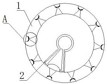
[0030] Such as Figure 1-3 As shown, the invention discloses a drum of a granulator, which includes a cylinder body 1 and an air injection mechanism 2. The cylinder body 1 has a cavity inside, and the air injection mechanism 2 is located in the cavity and is in sealing contact with the side wall of the cavity. The mechanism 2 does not rotate with the cylinder body 1, and the outer surface of the cylinder body 1 is provided with a granulation chamber 11, which communicates with the air injection mechanism 2. The structure sprays air through the air injection structure, so as to prevent the drum of the granulation equipment from being clogged by rolling, improve the granulation efficiency, and prevent the clogging of the drum surface.

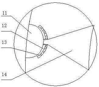
[0031] There is a tapered booster chamber 14 on the side wall of the cylinder body 1 , the output port of the booster chamber 14 communicates with the granulation chamber 11 , and the input port of the booster chamber 14 communicates with the air...

Embodiment 2

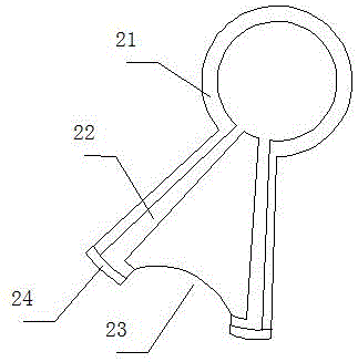
[0038] The invention discloses a drum of a granulator, which comprises a cylinder body 1 and an air injection mechanism 2. The cylinder body 1 has a cavity inside, and the air injection mechanism 2 is located in the cavity and is in sealing contact with the side wall of the cavity. The cylinder body 1 rotates, and a granulation chamber 11 is arranged on the outer surface of the cylinder body 1 , and the granulation chamber 11 communicates with the air injection mechanism 2 . The air injection mechanism 2 includes an air injection pipe 21, an air delivery channel 22, an air injection pipe 21 and a sealing portion 24; a conical booster chamber 14 and an elastic portion 12 are arranged on the rear side of the granulation chamber 11, and the elastic portion 12 is provided on the rear side The buffer chamber 13 is provided with an annular protrusion on the side wall of the buffer chamber 13; the output port of the pressurization chamber 14 is connected to and aligned with the granul...

Embodiment 3

[0041] Based on the structure of embodiment 1 or implementation 2, the anti-clogging method of its granulation cavity 11 is:

[0042] Step 1: After the barrel 1 rotates to the specified position, the gas gathering chamber 23 is aligned with a pressurized chamber 14, and the sealing part 24 is sealed with the inner side walls of the barrel 1 on both sides of the pressurized chamber 14;

[0043] Step 2: Inject air into the air injection pipe 21 at a speed of 0.1-0.15m³ / min, the air enters the gas gathering chamber 23 after passing through the air delivery channel 22, and generates an air pressure of 60-80pa at the detour to make the sealing part 24 close The inner wall of cylinder 1;

[0044] Step 3: After the air flow gathers through the pressurized part, it enters the granulation chamber 11 at a speed of 15-20m / s; when the granulation chamber 11 is blocked, the airflow compresses the elastic part 12, increasing the air pressure of the granulation chamber 11 until granulation ...


PUM


Abstract

The invention relates to the field of roller compaction granulation, in particular to a drum of a granulator. It includes a cylinder and an air injection mechanism. There is a cavity inside the cylinder. The air injection mechanism is located in the cavity and is in sealing contact with the side wall of the cavity. The air injection mechanism does not rotate with the cylinder. A granulation chamber is set on the outer surface of the cylinder. The chamber communicates with the jet mechanism. The structure sprays air through the air injection structure, so as to prevent the drum of the granulation equipment from being clogged by rolling, improve the granulation efficiency, and prevent the clogging of the drum surface. The air is injected through the air injection structure, so as to prevent the drum of the granulation equipment from being clogged by rolling, improve the granulation efficiency, and prevent the clogging of the drum surface. Utilize the speed and pressure of the rapidly entering airflow, and use the instantaneous air pressure to dredge the granulation cavity to ensure the effectiveness of the granulation cavity dredging; ensure that the granulation cavity can be dredged in time.

Description

technical field [0001] The invention relates to the field of roller compaction granulation, in particular to a drum of a granulator. Background technique [0002] Pellet mills can be divided into feed pellet machines and biomass energy pellet machines. Widely used in pharmaceutical, chemical and food industries. It is mainly composed of feeding, stirring, granulating, transmission and lubrication systems. Its working process is to require the compound powder with a water content of not more than 15%, enter the feeding auger from the hopper, adjust the speed of the stepless speed regulating motor to obtain a suitable material flow, and then enter the agitator, and stir it with the steam through the stirring rod. Mix and temper. If you need to add molasses or oil, add it from the mixing drum and steam together. The amount of oil added generally does not exceed 3%, otherwise it will be difficult to form. After conditioning, the temperature of the mixed powder can reach 64-85°...

Claims


Application Information

Patent Timeline
Patent Type & Authority Applications(China)
IPC IPC(8): B01J2/22
CPCB01J2/22
Inventor 程政
Owner 成都测迪森生物科技有限公司
Why Eureka
Try Eureka