Drawing die and drawing system for metal wire

A metal wire and mold technology, applied in the direction of wire drawing die, etc., can solve problems such as inappropriate compression angle, difficulty in drawing metal wire performance, and short service life of molds

Active Publication Date: 2016-12-07
NANTONG HUIFENG ELECTRONICS TECH
View PDF9 Cites 4 Cited by
  • Summary
  • Abstract
  • Description
  • Claims
  • Application Information

AI Technical Summary

Problems solved by technology

[0006] Therefore, the technical problem to be solved by the present invention is that the angle of the compression angle of the compression zone of the drawing die in the prio

Method used


Image

  • Drawing die and drawing system for metal wire
  • Drawing die and drawing system for metal wire
  • Drawing die and drawing system for metal wire

Examples


Embodiment 1

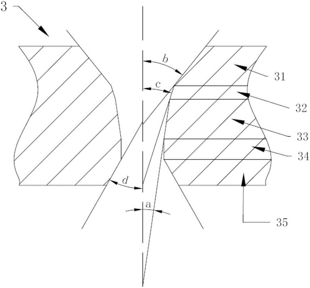
[0053] The present embodiment provides a drawing die 3, such as figure 1 As shown, it includes a conical inlet zone 31, a lubricating zone 32, a conical compression zone 33, a cylindrical sizing zone 34 and a conical outlet zone 35 connected in sequence by a circular arc transition;

[0054] The conical inlet zone 31, lubricating zone 32, conical compression zone 33, cylindrical sizing zone 34, and conical outlet zone 35 all have inner holes for metal wires to pass through;

[0055] The diameter of the inner hole gradually decreases from the entrance of the conical inlet zone 31 to the exit of the compression zone 33, and gradually increases from the entrance of the conical exit zone 35 to its exit;

[0056] The angle of the taper angle of the mold gradually decreases from the tapered entrance area 31 to the compression area 33, and the angle of the taper angle (compression angle) 2a of the compression area 33 is 5°-12°. For example, 5°, 5.3°, 5.8°, 6°, 6.5°, 7°, 7.2°, 7.8°, ...

Embodiment 2

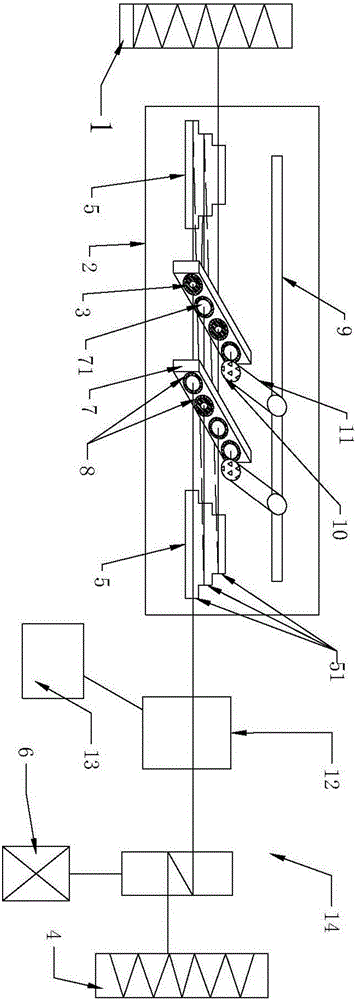
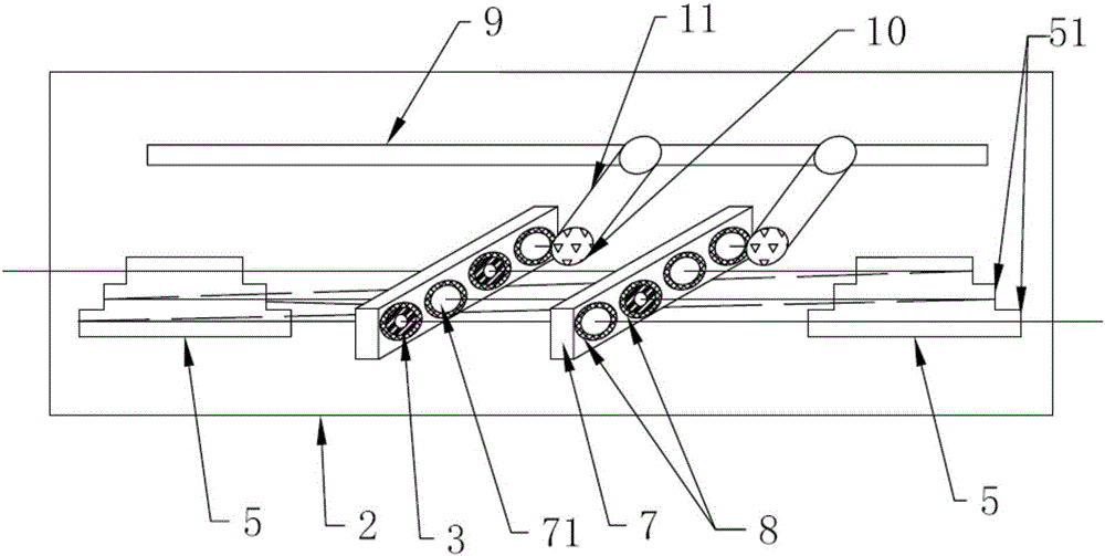
[0066] The invention provides a metal wire drawing system, such as figure 2 and image 3 shown, including

[0067] Wire pay-off device 1, used for winding the first metal wire to be drawn;

[0068] The drawing box body 2 has a cavity, a wire inlet and a wire outlet;

[0069] A support seat 7 is obliquely arranged on the inner wall of the drawing box 2, and a plurality of installation holes 71 are opened along its length direction, and any one of the drawing dies 3 recorded in Embodiment 1 is arranged in the installation holes 71;

[0070] The pulling device is used to continuously extract one end of the first metal wire from the pay-off device 1, and is drawn into a second metal wire of a required diameter through the drawing die 3;

[0071] The wire take-up device 4 is used to collect the drawn second metal wire.

[0072] The metal wire drawing system of this structure is provided with a plurality of installation holes 71 on the support base 7, and any one of the drawing...


PUM

PropertyMeasurementUnit
Angleaaaaaaaaaa

Abstract

The invention discloses a drawing die and a drawing system for a metal wire. The drawing die comprises a tapered inlet region, a lubricating region, a tapered compression region, a cylindrical sizing region and a tapered outlet region which are sequentially connected through a circular arc transition portion; and the angle of the taper angle of the die decreases gradually from the tapered inlet region to the compression region, and the angle of the taper angle of the compression region ranges from 5 degrees to 12 degrees. The drawing system comprises a pay-off device, a drawing box body, at least one supporting seat, a traction device and a take-up device. The supporting seats are obliquely arranged on the inner wall of the drawing box body. The drawing die is mounted in mounting holes of the supporting seats. When the metal wire passes the compression region of the drawing die, compared with a drawing die in the prior art, by the adoption of the drawing die and the drawing system, if the same metal wire compression rate and the small reduction of the area are reached, the required traction force provided by the traction device is minimum, the loss of the internal gold phase structure of the metal wire material is small, a die core is not destroyed, the service life of the drawing die is prolonged, and the surface of the drawn metal wire is smooth.

Description

technical field [0001] The invention relates to the technical field of metal material processing and preparation, in particular to a drawing die and a metal wire drawing system. Background technique [0002] At present, when the metal wire is drawn in the prior art, the structure of the metal wire drawing system mainly includes a pay-off reel, a drawing groove and a pulling device, wherein the drawing groove is located between the pay-off reel and the pulling device. In between, a number of drawing dies are set in the drawing groove, and the metal wire is wound on the pay-off reel. Under the continuous stretching action of the traction device, the metal wire passes through the drawing die and is then thinned to the required diameter. . [0003] The quality of metal drawing by the drawing system mainly depends on the structure of the drawing die. The structure of the drawing die mainly includes a conical entrance area, a conical compression area, a sizing area and a conical ...

Claims


Application Information

Patent Timeline
IPC IPC(8): B21C3/04B21C1/04B21C1/14
CPCB21C1/04B21C1/14B21C3/04
Inventor 石明华蔡成俊陈健宋小波
Owner NANTONG HUIFENG ELECTRONICS TECH
Why Eureka
Try Eureka