Positioning method of flexible tool in forming process of composite product

A composite material and positioning method technology, which is applied in the field of high-performance carbon fiber composite structural parts manufacturing, can solve the problems of scrapped parts, position deviation of soft tooling, position deviation of thickening area, etc., to ensure surface forming quality, The effect of improving the qualified rate and improving production efficiency

Inactive Publication Date: 2016-12-07
航天海鹰(镇江)特种材料有限公司
View PDF6 Cites 9 Cited by
  • Summary
  • Abstract
  • Description
  • Claims
  • Application Information

AI Technical Summary

Problems solved by technology

[0006] Soft tooling generally uses rubber as the main material, and the overall rigidity is poor, and it cannot be mechanically positioned with the forming tooling. Therefore, during the molding process of composite parts, the position of the soft tooling often shifts
If the part to be formed has elements such as thickened areas, once the position of the soft tooling deviates, it will inevitably affect the surface quality and contour of the part after molding, and cause the position deviation of the thickened area. In severe cases, it may lead to scrap

Method used


Image

  • Positioning method of flexible tool in forming process of composite product
  • Positioning method of flexible tool in forming process of composite product
  • Positioning method of flexible tool in forming process of composite product

Examples


Embodiment Construction

[0025] The present invention will be further described below in conjunction with the accompanying drawings and specific embodiments.

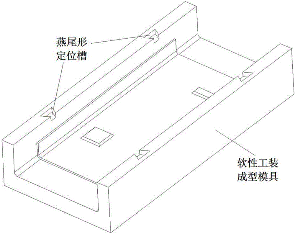
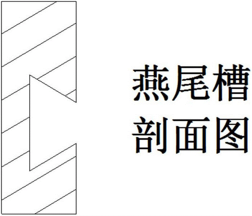
[0026] The present invention molds the soft tooling through a metal mold. The forming mold is provided with dovetail-shaped positioning grooves, and the positioning grooves are symmetrically distributed on both sides of the mould. The quantity and specifications need to be determined in combination with the size and structural complexity of the composite material parts, such as figure 1 and 2 .

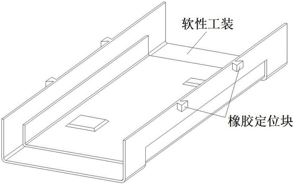
[0027] When laying soft tooling, fill the dovetail groove with rubber and connect it with the soft tooling, so that after the soft tooling is solidified, a certain number of dovetail-shaped rubber positioning blocks will be attached to the edge, such as image 3 .

[0028] There are also several dovetail-shaped positioning grooves on the molding die of composite material parts, and the size specifications and positions are consistent with the soft to...


PUM


Abstract

The invention discloses a positioning method of a flexible tool in a forming process of a composite product. The positioning method comprises the following steps: more than two dovetail-shaped positioning grooves are respectively formed in two sides of a flexible tool forming mold; a metal false piece is placed on the surface of the flexible tool forming mold; when the flexible tool is laid and adhered to the surface of the metal false piece, the dovetail-shaped grooves are filled with rubber, the rubber is connected with the flexible tool, the outside of the flexible tool is sealed under vacuum by a vacuum bag, and then the sealed flexible tool enters an autoclave for forming; after a rubber flexible mold is formed, the vacuum bag is removed, the metal false piece is taken out, the shaped flexible tool is filled with composites, then the outer layer of the shaped flexible tool is sealed under vacuum by the vacuum bag, and the flexible tool enters the autoclave for forming to obtain the composite product. By the dovetail-shaped positioning groove structure, positioning between the flexible tool and the forming mold is finished, the flexible tool is fixed and does not deviate in the forming process of the composite product, and therefore, the surface forming quality of the composite product is guaranteed.

Description

technical field [0001] The invention belongs to the technical field of advanced composite material manufacturing, and in particular relates to the manufacturing of high-performance carbon fiber composite structural parts in the industry of aircraft, spacecraft and automobiles. Background technique [0002] Resin-based carbon fiber composite materials have superior properties such as specific strength and specific stiffness, strong designability, good fatigue fracture resistance, corrosion resistance, and good dimensional stability. They are currently widely used in aviation, aerospace, transportation and other fields. High-performance structural materials. Among various carbon fiber composite molding processes, the autoclave process has uniform molding temperature and pressure, and has good adaptability to parts of different materials, shapes, sizes and structures. One of the main process methods of material components. [0003] The U-shaped web is a representative structu...

Claims


Application Information

Patent Timeline
Patent Type & Authority Applications(China)
IPC IPC(8): B29C70/54
CPCB29C70/541
Inventor 贾傲黎玉钦王国平高志强左扬马秀菊刘备备邓延强宏军
Owner 航天海鹰(镇江)特种材料有限公司
Why Eureka
Try Eureka