Automobile rearview optical assembly

A technology for optical components and rearview mirror components, applied in the field of vehicles, can solve the problems of high cost, difficult to meet actual needs, complex structure, etc.

Inactive Publication Date: 2016-12-07
方流生
View PDF0 Cites 0 Cited by
  • Summary
  • Abstract
  • Description
  • Claims
  • Application Information

AI Technical Summary

Problems solved by technology

However, some existing adjustable optical rearview systems often have complex structures and high costs, and are difficult to meet actual needs.

Method used


Image

  • Automobile rearview optical assembly
  • Automobile rearview optical assembly
  • Automobile rearview optical assembly

Examples


Embodiment Construction

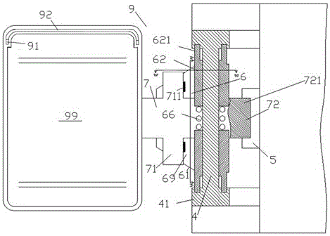
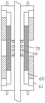
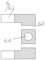
[0010] Combine below Figure 1-4 The present invention will be described in detail.

[0011] The automobile rearview optical assembly according to the embodiment includes a rearview mirror assembly 9 installed on the fixed shaft 4 of the vehicle. The fixed base 5 is fixedly connected with the vehicle body and includes an elastic material, which is slidably installed on the vehicle fixed shaft 4 and symmetrically arranged on the fixed base 5. The two rotation locking sliders 6 on the upper and lower sides of the two fixing plates 7, each of the rotation locking sliders 6 includes a sleeve part 62 sleeved on the vehicle fixing shaft 4 and a front and rear separately arranged. and fixed on the two inclined plates 69 at the front and rear sides of the sleeve part 62; wherein, the outer side of the sleeve part 62 is provided with a rotation preventing bayonet pin 621 for extending into the fixed position of the vehicle. In the bayonet hole in the rotation prevention chuck 41 on t...


PUM


Abstract

An automotive rearview optical assembly, comprising a rearview mirror assembly (9) installed on a vehicle fixed shaft (4), the rearview mirror assembly (9) including: The two fixed plates (7) are arranged in the front and back of the fixed base (5) which are set apart in a sliding manner; Two sliding blocks (6) for rotation locking are arranged symmetrically on the upper and lower sides of the two fixing plates (7) on the vehicle fixing shaft (4).

Description

technical field [0001] The invention relates to the field of vehicles, in particular to an automotive rearview optical assembly. Background technique [0002] Vehicle rearview optical systems, such as rearview mirror assemblies, play an important role in driving safety. However, in the course of use, it is necessary to fix the selected angle of the rearview mirror, so as to avoid unintentionally changing the rotation angle of the rearview mirror and thereby affecting driving safety. Select and adjust driving habits and sitting posture. However, some existing adjustable optical rearview systems often have complex structures and high costs, and are difficult to meet actual needs. Contents of the invention [0003] The object of the present invention is to provide an automotive rearview optical assembly, which can overcome the defects in the prior art. [0004] According to the automobile rearview optical assembly of the present invention, it includes a rearview mirror ass...

Claims


Application Information

Patent Timeline
Patent Type & Authority Applications(China)
IPC IPC(8): B60R1/06
CPCB60R1/06
Inventor 方流生
Owner 方流生
Why Eureka
Try Eureka