A power bogie driven by a DC motor

A power bogie and DC motor technology, applied in bogies, motor vehicles, electric locomotives, etc., can solve the problems of uneven driving force, easy slipping of wheels and tracks, fast wear of driving wheels, etc., and achieve a simple and practical overall structure, The steering structure is simple and practical, and the effect of ensuring stability

Active Publication Date: 2018-07-10
ZHUZHOU CSR SPECIAL EQUIP TECH
View PDF6 Cites 0 Cited by
  • Summary
  • Abstract
  • Description
  • Claims
  • Application Information

AI Technical Summary

Problems solved by technology

[0002] In the prior art, the structure of the power bogie is complicated, and most of them are unilaterally driven by the motor through the transmission, and there is only one driving wheel. On the one hand, the output torque of the motor is not fully utilized, which makes it easy to slip between the wheels and the track, resulting in poor climbing ability of the vehicle. In terms of driving, the power provided by the motor cannot be fully converted. On the one hand, it is a serious waste of energy. In addition, this traditional structure will cause a lot of loss to the wheels and tracks, which does not meet the production needs of modern sustainable development and efficient transformation.

Method used


Image

  • A power bogie driven by a DC motor
  • A power bogie driven by a DC motor
  • A power bogie driven by a DC motor

Examples


Embodiment Construction

[0017] The present invention will be further described in detail below in conjunction with the accompanying drawings and embodiments.

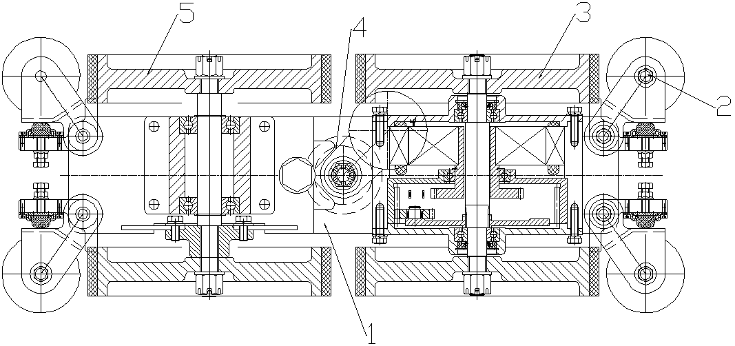
[0018] Such as figure 1 As shown, the present invention is achieved through the following technical solutions: a power bogie driven by a DC motor, including a base 1, a guide unit 2, a drive unit 3, a steering unit 4, and a driven unit 5. Four guide units 2 are respectively arranged on the four corners of the upper part of the seat 1, a driving unit 3 is arranged in front of the upper part of the base 1, a driven unit 5 is arranged at the rear of the upper part of the base 1, and a driven unit 5 is arranged at the rear of the upper part of the base 1. 1. A steering unit 4 is provided in the middle of the upper part. The driving unit 3 is connected to the two guiding units 2 in the front, and the driven unit 5 is connected to the two guiding units 2 in the rear. The front end of the steering unit 4 is connected to The driving unit 3 is connect...


PUM


Abstract

The invention relates to a power bogie driven by a direct current motor. The power bogie comprises a base, guide units, a driving unit, a steering unit and a driven unit. The guide units are arranged at four endpoints of the upper portion of the base correspondingly. The driving unit is arranged on the front of the upper portion of the base. The driven unit is arranged on the rear of the upper portion of the base. The steering unit is arranged in the middle of the upper portion of the base. The power bogie is simple and practical in steering structure, achieves balanced driving and can reduce abrasion.

Description

technical field [0001] The invention relates to a steering device driven by a DC motor, in particular to a power bogie driven by a DC motor. Background technique [0002] In the prior art, the structure of the power bogie is complicated, and most of them are unilaterally driven by the motor through the transmission, and there is only one driving wheel. On the one hand, the output torque of the motor is not fully utilized, which makes it easy to slip between the wheels and the track, resulting in poor climbing ability of the vehicle. In terms of driving, the power provided by the motor cannot be fully converted. On the one hand, it is a serious waste of energy. In addition, this traditional structure will cause a lot of loss to the wheels and tracks, which does not meet the production needs of modern continuous development and efficient transformation. Contents of the invention [0003] The purpose of the present invention is to overcome the deficiencies in the prior art a...

Claims


Application Information

Patent Timeline
Patent Type & Authority Patents(China)
IPC IPC(8): B61F5/00B61C3/00
CPCB61C3/00B61F5/00
Inventor 刘兵廖巧云吴启舟
Owner ZHUZHOU CSR SPECIAL EQUIP TECH
Why Eureka
Try Eureka