
Concrete prefabricated groove

A concrete and groove technology, applied in water conservancy projects, artificial islands, ground cable installation, etc., can solve the problems of large U-shaped grooves, difficult to reduce costs, increase construction costs, etc., achieve light weight, reduce transportation costs, improve The effect of efficiency

Inactive Publication Date: 2016-12-07
中建科技(福州)有限公司
View PDF5 Cites 5 Cited by
  • Summary
  • Abstract
  • Description
  • Claims
  • Application Information

AI Technical Summary

Problems solved by technology

However, U-shaped prefabricated cable trenches still have many disadvantages: the size is fixed, and specific molds need to be developed for each trench size, which is difficult to reduce the cost. Secondly, the U-shaped trench is bulky and inconvenient to transport, which further increases the construction cost

Method used


Image

  • Concrete prefabricated groove
  • Concrete prefabricated groove
  • Concrete prefabricated groove

Examples


Embodiment Construction

[0035] The present invention will be described in detail below in conjunction with the accompanying drawings and specific embodiments.

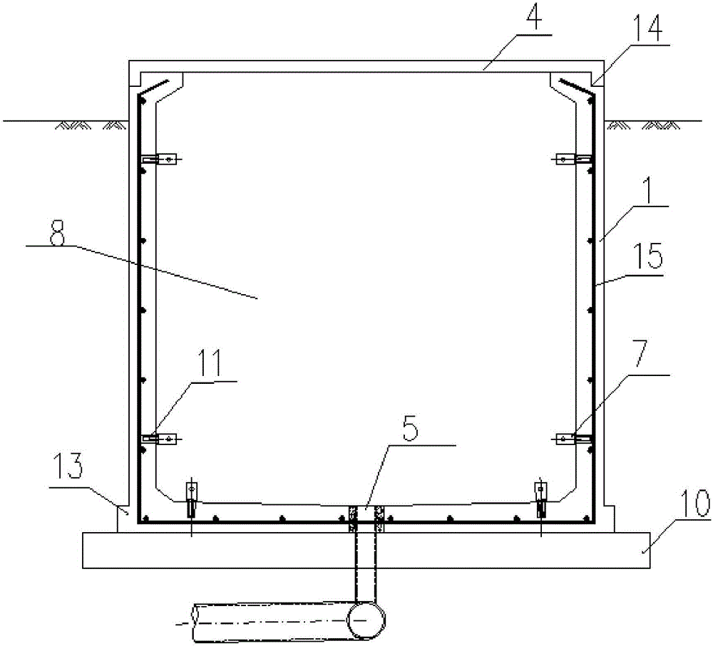
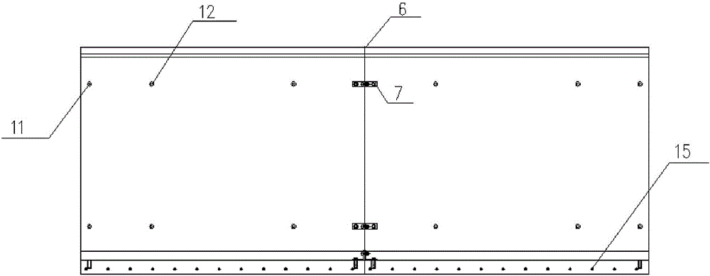
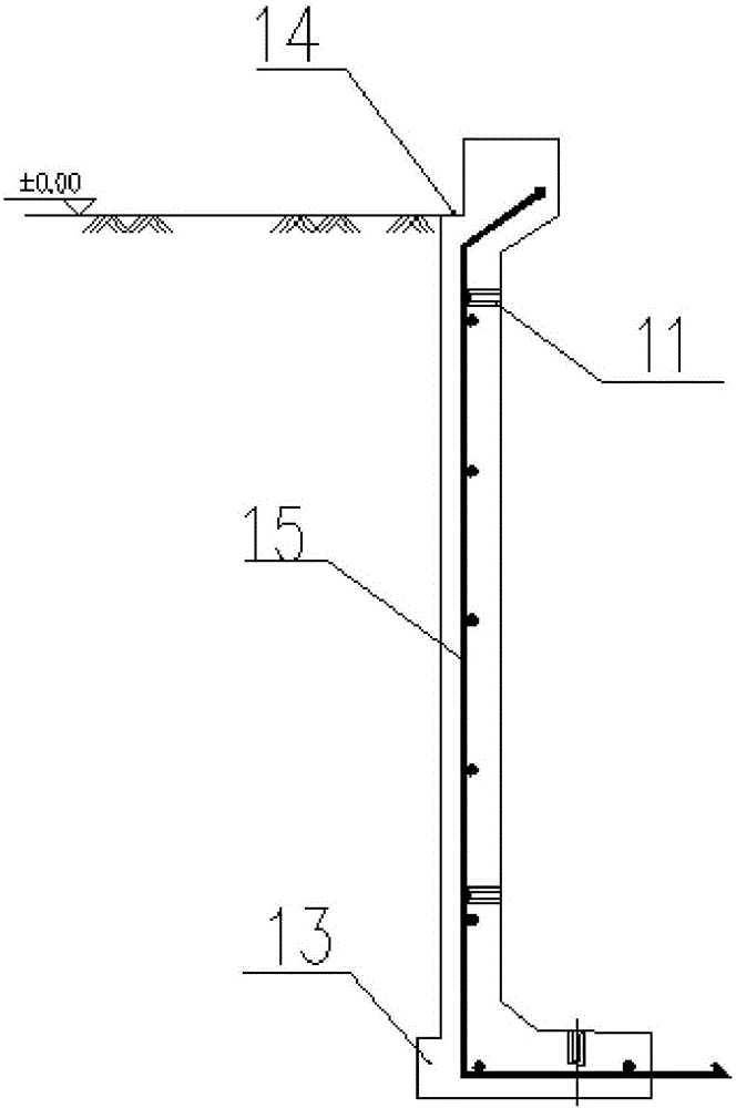
[0036] see Figure 1-4 , a concrete prefabricated groove, including an L-shaped member 1, a cover plate 4, a downpipe 5, an expansion water stop strip 6 and a connecting block 7; two L-shaped members 1 are overlapped in parallel to form a U-shaped groove 8, A concrete post-cast belt is formed at the lap; the bottom of the vertical groove 8 of the downpipe 5 is arranged at the overlap of the two L-shaped members 1; the cover plate 4 is covered on the upper part of the groove 8; the L-shaped member 1 Both ends are respectively provided with a plurality of ditch connecting holes 11; the ditch connecting holes 11 are connected with the connecting block 7; Figure 8 , a plurality of L-shaped components 1 are connected end to end through the connecting block 7 to realize linear extension; the expansion water-stop strip 6 is arranged at the junctio...


PUM


Abstract

The invention relates to a concrete prefabricated groove. The concrete prefabricated groove comprises a groove body. The groove body is formed through opposite lap joint of two L-shaped components in parallel. A sewer pipe is perpendicular to the bottom of the groove body and is arranged at the lap joint position of the two L-shaped components. The upper portion of the groove body is covered with a cover plate. The concrete prefabricated groove can adapt to different cable trench widths, and the research and development number of dies is reduced. The size is small, the concrete prefabricated groove is easier to tidy and stack during transportation compared with U-shaped components, and the transportation cost is effectively reduced; and assembling is flexible, and the concrete prefabricated groove can adapt to the arrangement of different lines.

Description

technical field [0001] The invention relates to a construction prefabricated structure, in particular to a concrete prefabricated trench. Background technique [0002] With the acceleration of the construction of modern international cities, urban power lines and communication lines are gradually transferred from the ground to the ground. In order to bury cables, generally there must be a U-shaped cable trench (or cable trench) in the cross section. A cable support protrudes from the side wall, and a cover plate is also provided on the wire trench. [0003] Traditional cable trenches often use brick-laying cable trenches or cast-in-place concrete cable trenches, and the cable brackets are directly embedded in the wall during masonry. Since the main material of masonry is solid clay red brick, it causes waste of land resources and is a non-degradable resource consumption product, which has been gradually limited or even banned in large, medium and small cities. Moreover, on...

Claims


Application Information

Patent Timeline
Patent Type & Authority Applications(China)
IPC IPC(8): E02D29/045H02G9/02
CPCE02D29/045H02G9/02
Inventor 卢恒王耀涂闽杰张家钦刘影杨文斌周勇庞二波易伟夏江波陈志军谢祖光
Owner 中建科技(福州)有限公司
Learn More