Dead bolt pop-up device

A technology of pop-up device and square tongue, which is applied in the direction of building locks, buildings, building structures, etc., can solve the problems of safety problems, two-way sliding tongue pressing back and large force of pop-up, and large force required to close the door, so as to achieve simple structure, Reduce lock body wear and prolong service life

Active Publication Date: 2016-12-07
ALLEGION SECURITY TECH CHINA
View PDF6 Cites 6 Cited by
  • Summary
  • Abstract
  • Description
  • Claims
  • Application Information

AI Technical Summary

Problems solved by technology

The first method is in the pop-up state when the square tongue is not aligned with the hole of the door frame, asynchronous pop-up, the square tongue and the door frame are easily damaged, and false locks are prone to occur, resulting in safety problems
The second way is to control the synchronous ejection through the linkage mechanism. For example, the Chinese invention patent application number 201010108908.6 discloses a two-way locking tongue triggering the main tongue synchronous ejection device. Although this method avoids the shortcomings of the first method, However, new disadvantages have been added. The two-way sliding tongue has too much force to press back and pop up, and it takes a lot of force to close the door.
And there are too few effective locking points, which does not meet the national standard

Method used


Image

  • Dead bolt pop-up device
  • Dead bolt pop-up device
  • Dead bolt pop-up device

Examples


Embodiment Construction

[0048] In order to better illustrate the present invention, it will be described below with reference to the accompanying drawings.

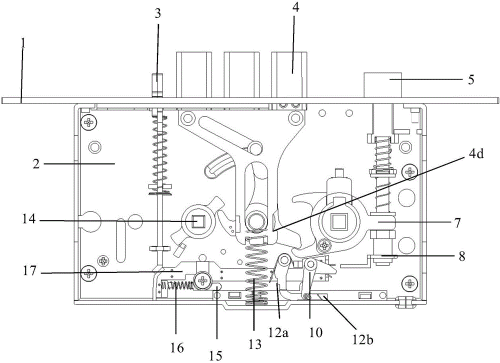
[0049] figure 1 An embodiment of the present invention is shown, which shows the state when the state tongue assembly, the square tongue assembly, and the oblique tongue assembly are all stretched out. according to figure 1 As shown, the status tongue assembly 3, the square tongue assembly, and the oblique tongue assembly 5 all protrude from the side panel. The inclined-plane of state tongue 3 afterbody just in time is opposite with the inclined-plane of slide plate 17 left sides. At this time, the slide plate is located on the far left side, and the spring is also in a natural state. Of course, it can be understood that the spring one can also be in a slightly compressed state at this time, so that the slide plate can be guaranteed to move to the left after the square tongue 4 is stretched out. . One end of the spring is fixed on the slide ...


PUM


Abstract

The invention discloses a dead bolt pop-up device. When a door is closed, a dead bolt can be triggered to pop up automatically and synchronously through cooperation of a state bolt assembly and a latch bolt assembly. The dead bolt pop-up device is provided with a dead bolt check piece, a latch bolt dial driving piece, a sliding plate, a first spring, a second spring and a third spring, wherein the dead bolt check piece is used for clamping and locking the dead bolt to enable the dead bolt to be in a retracted state; the latch bolt dial driving piece can drive the dead bolt check piece to carry out clamping and locking so that the dead bolt can pop up; the sliding plate is used for driving the latch bolt dial driving piece to move towards a latch bolt when the state bolt assembly retracts, and driving the latch bolt dial driving piece to move opposite to the latch bolt when the state bolt assembly stretches; the first spring is connected with the sliding plate and is in a natural state when the state bolt assembly stretches; the second spring is connected with the dead bolt check piece and is in a natural state when the dead bolt is clamped and locked; and the third spring is connected with the latch bolt dial driving piece and is not in a natural state when the latch bolt dial driving piece applies driving force to the dead bolt check piece.

Description

technical field [0001] The invention relates to a mortise lock body, in particular to a square tongue synchronous automatic ejection device. Background technique [0002] Present anti-theft locks are generally provided with a plurality of dead bolts, such as oblique bolts, square bolts and the like. There are basically three ways to eject the square tongue when closing the door: 1. Use the key to eject the square tongue, 2. Lift the handle to eject the square tongue, 3. The square tongue will automatically eject. [0003] There are generally two ways to automatically eject the square tongue: 1. When the door is closed, when the latch tongue starts to advance, it is in the ejected state; 2. The realization method of synchronous ejection is controlled by the linkage mechanism. In the first way, because the square tongue is not aligned with the hole of the door frame, it is in the pop-up state, and the non-synchronous pop-up, the square tongue and the door frame, etc. are easi...

Claims


Application Information

Patent Timeline
Patent Type & Authority Applications(China)
IPC IPC(8): E05B63/20E05B15/12E05B15/00E05B63/14
CPCE05B15/00E05B63/146E05B63/20
Inventor 刘锋
Owner ALLEGION SECURITY TECH CHINA
Why Eureka
Try Eureka