Pre-positioning Mechanism of Furniture Damping Device
A damping device and pre-positioning technology, which is applied to the suspension device of the wing fan, the building component, the layout of the wing fan, etc., can solve the problems of the complex structure of the automatic opening device, the inability to meet the needs of users, and the lack of position adjustment. Small shaking, improving the internal use position, and the effect of structural stability
- Summary
- Abstract
- Description
- Claims
- Application Information
AI Technical Summary
Problems solved by technology
Method used
Image
Examples
no. 1 example
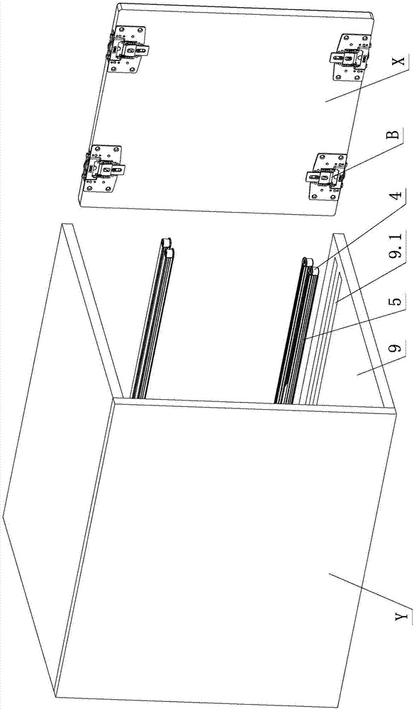
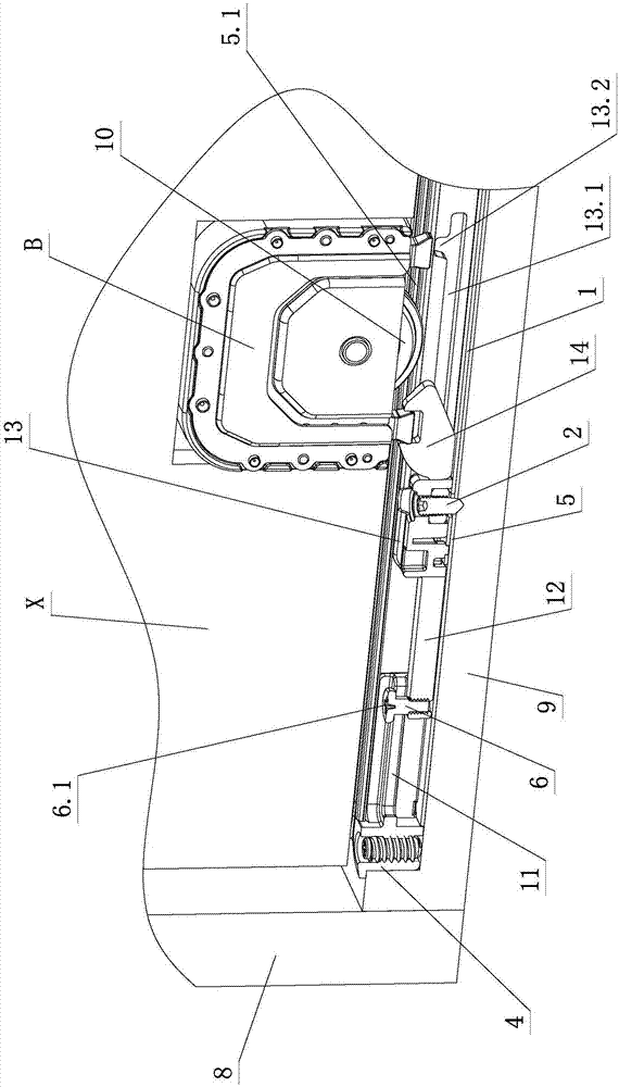
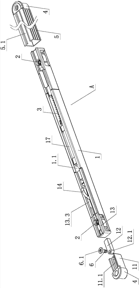
[0030] see Figure 1-Figure 4 , the pre-positioning mechanism of the furniture damping device includes a damping device A, the damping device A at least includes a fixed bracket 1, a damper, a positioning unit 2 and a return spring 3, the damper is connected with the return spring 3, and through the return spring 3 The positioning slides on the fixed bracket 1, the positioning unit 2 is arranged on the fixed bracket 1, and also includes a fixed element 4 and a fixed groove part 5, and the fixed element 4 and the damping device A are arranged on the fixed groove part 5, wherein the fixed element 4 and / or Or the damping device A is provided with a pre-positioning adjustment assembly, the damping device A and the fixing element 4 are set relatively independently, and the relative positions of the two are adjusted through the adjustment and positioning of the pre-positioning adjustment assembly.
[0031] Furthermore, the pre-positioning adjustment assembly is integrally formed or ...
no. 2 example
[0041] see Figure 5, the pre-positioning mechanism of this furniture damping device is different from the first embodiment in that: the adjustment element is an adjustment screw 6, and an elastic action part 6.1 is arranged on it, and one end of the chute member 11 is integrally formed on the fixed element 4, the other end is provided with a sliding part 11.1, one end of the guide 12 is slidably arranged on the sliding part 11.1, and the other end is integrally formed on the damping device A, the guide 12 is also provided with a hole 12.1, and the adjustment screw 6 is positioned and rotated On the hole 12.1; through the tool or manual action of the elastic action part 6.1, the adjustment screw 6 is positioned and rotated, and the guide 12 is fixed on the sliding part 11.1 through the cooperation of the hole 12.1 and the adjustment screw 6; through the tool or manual action of the elastic action part 6.1, the adjustment screw 6 is positioned and rotated, the guide 12 and the ...
no. 3 example
[0044] see Image 6 , the pre-positioning mechanism of this furniture damping device is different from the first embodiment in that: the adjusting element is an adjusting screw 6, and an elastic action part 6.1 is arranged on it, and one end of the chute member 11 is integrally formed on the damping device On A, the other end is provided with a sliding part 11.1, one end of the guide 12 is slidably arranged on the sliding part 11.1, and the other end is separately arranged on the fixing element 4, the guide 12 is also provided with a hole 12.1, and the adjustment screw 6 is positioned Rotate on the hole part 12.1; through the tool or manual action of the elastic part 6.1, the adjustment screw 6 is positioned and rotated, and the guide 12 is fixed on the sliding part 11.1 through the cooperation of the hole part 12.1 and the adjustment screw 6; through the tool or manual action of the elastic action Part 6.1, the adjusting screw 6 is positioned and rotated, the guide 12 and the...
PUM
 Abstract
Description
Claims
Application Information
 - R&D
- Intellectual Property
- Life Sciences
- Materials
- Tech Scout
- Unparalleled Data Quality
- Higher Quality Content
- 60% Fewer Hallucinations
Browse by: Latest US Patents, China's latest patents, Technical Efficacy Thesaurus, Application Domain, Technology Topic, Popular Technical Reports.
© 2025 PatSnap. All rights reserved.Legal|Privacy policy|Modern Slavery Act Transparency Statement|Sitemap|About US| Contact US: help@patsnap.com


