A rotary engine and its working method

A technology of rotary engine and working method, which is applied to combustion engines, machines/engines, internal combustion piston engines, etc., which can solve the problems of low thermal efficiency, ineffective work, and short combustion time of the engine, and achieve long combustion time and low mechanical strength requirements , The effect of low machining requirements

Active Publication Date: 2018-09-04
王衍超
View PDF5 Cites 0 Cited by
  • Summary
  • Abstract
  • Description
  • Claims
  • Application Information

AI Technical Summary

Problems solved by technology

The disadvantages of existing rotary engines are: the combustion time is short and the combustion is incomplete; the lubrication method is splash lubrication, the oil consumption is large, and the oil is discharged with the exhaust gas, and the emission exceeds the standard
[0005] When natural gas is used as fuel, both engines have the following disadvantages: 1) The combustion time is short, resulting in fuel after-combustion, which cannot effectively perform work; 2) The exhaust temperature is high, resulting in low thermal efficiency of the engine; 3) It is prone to knocking, which seriously affect machine work

Method used


Image

  • A rotary engine and its working method
  • A rotary engine and its working method
  • A rotary engine and its working method

Examples


Embodiment Construction

[0044] The present invention will be further explained below in conjunction with the accompanying drawings.

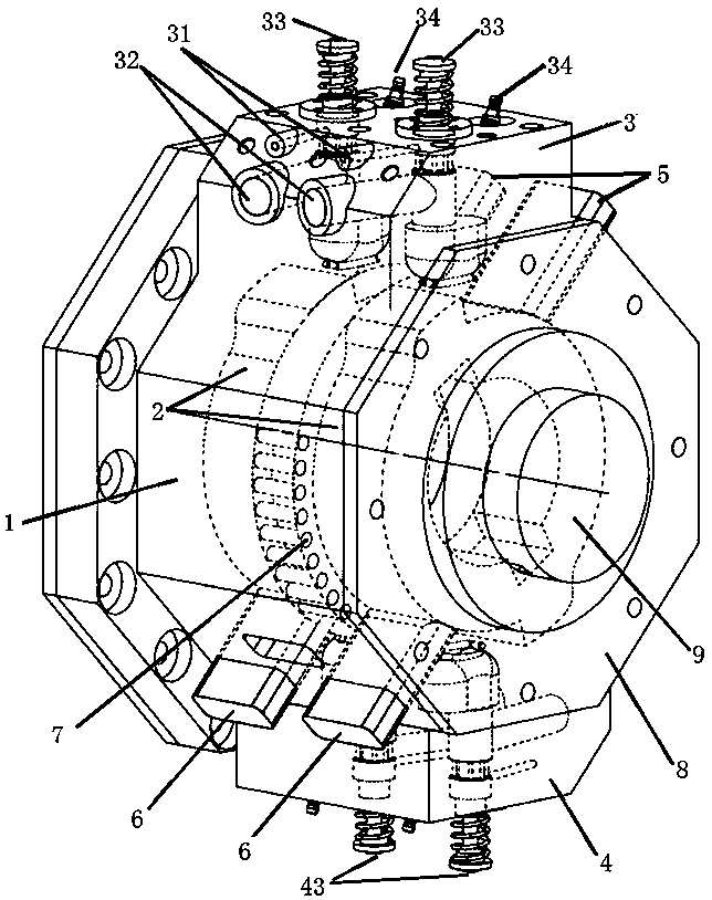
[0045] like Figure 3 to Figure 5 As shown, a rotary engine includes a set of power modules for outputting power. The power modules include a casing 1, an end cover 8, two cylinder heads installed on the casing 1, and two rotor units. The above-mentioned two cylinder heads are symmetrically distributed at the upper and lower positions of the casing 1, that is, the upper cylinder head 3 and the lower cylinder head 4 in the figure, and the N rotor units are arranged in the casing 1 sequentially. A baffle is arranged between adjacent rotor units, and a plurality of small holes 7 for passing air between the rotor units are arranged on the baffle.

[0046] The above-mentioned rotor unit includes a rotor 2, the rotor 2 is circular, the outer diameter of the rotor 2 is smaller than the inner cavity diameter of the casing 1 and two protrusions are arranged symmetrically in th...


PUM


Abstract

The invention relates to the field of internal combustion engines, in particular to a rotor engine and a working method thereof. The rotor engine comprises at least one set of power modules for outputting power; the power modules include shells, end covers, two cylinder covers mounted on the shells, and N rotor units; the two cylinder covers are distributed in the upper and lower positions of the shells in a center symmetry manner; the N rotor units are arranged in the shells in sequence front and back; separation plates are arranged between the adjacent rotor units, and are provided with multiple air crossing small holes for ventilation among the rotor units; and N is a natural number not smaller than 2.

Description

technical field [0001] The invention relates to the field of internal combustion engines, in particular to a rotary engine and a working method thereof. Background technique [0002] In the prior art, engines mainly include reciprocating engines and rotary engines, both of which rely on the expansion pressure generated by the combustion of air-fuel mixture to obtain rotational force. [0003] like figure 1 As shown, the four-stroke reciprocating engine requires the piston to reciprocate in the cylinder, and the crankshaft is driven by the crank-link mechanism. The disadvantage of this method is that the connecting parts of the mechanical parts are subjected to a large impact load, and the mechanical noise generated is large. The mechanical strength, machining accuracy and lubrication requirements are all high. [0004] like figure 2 As shown, the rotary engine is mainly the triangular rotary engine of Mazda Company. This engine directly pushes the pressure generated by t...

Claims


Application Information

Patent Timeline
Patent Type & Authority Patents(China)
IPC IPC(8): F02B53/00F02B55/02F02B55/16
CPCF02B53/00F02B55/02F02B55/16Y02T10/12
Inventor 王衍超
Owner 王衍超
Why Eureka
Try Eureka