A sucker plate

A pressure plate and suction cup technology, applied in suction cups, connecting components, mechanical equipment, etc., can solve the problems of too large and too small rebound force of the suction cup cover.

Active Publication Date: 2018-12-04
ZHONGSHAN TAILI HOUSEHOLD PROD MFG
View PDF9 Cites 0 Cited by
  • Summary
  • Abstract
  • Description
  • Claims
  • Application Information

AI Technical Summary

Problems solved by technology

[0007] The purpose of the present invention is to overcome the problem that the rebound force of the suction cup cover in the prior art is too small or too large, and provide a suction cup cover with a suitable rebound force

Method used


Image

  • A sucker plate
  • A sucker plate
  • A sucker plate

Examples


Embodiment Construction

[0022] Embodiments of the present invention are described in detail below in conjunction with specific embodiments:

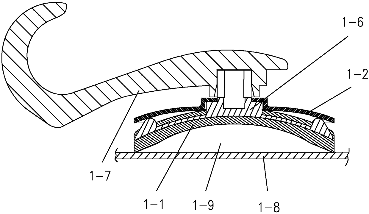
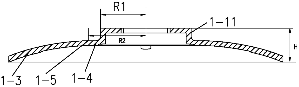
[0023] A suction cup pressing plate, which comprises a curved surface pressing plate 1-3 and a positioning platform 1-11, the positioning platform is located in the middle of the suction cup pressing plate, there is a planar central surface 1-4 between the positioning platform and the curved surface pressing plate, the positioning platform and the curved surface pressing plate, The center surface is integrally formed.

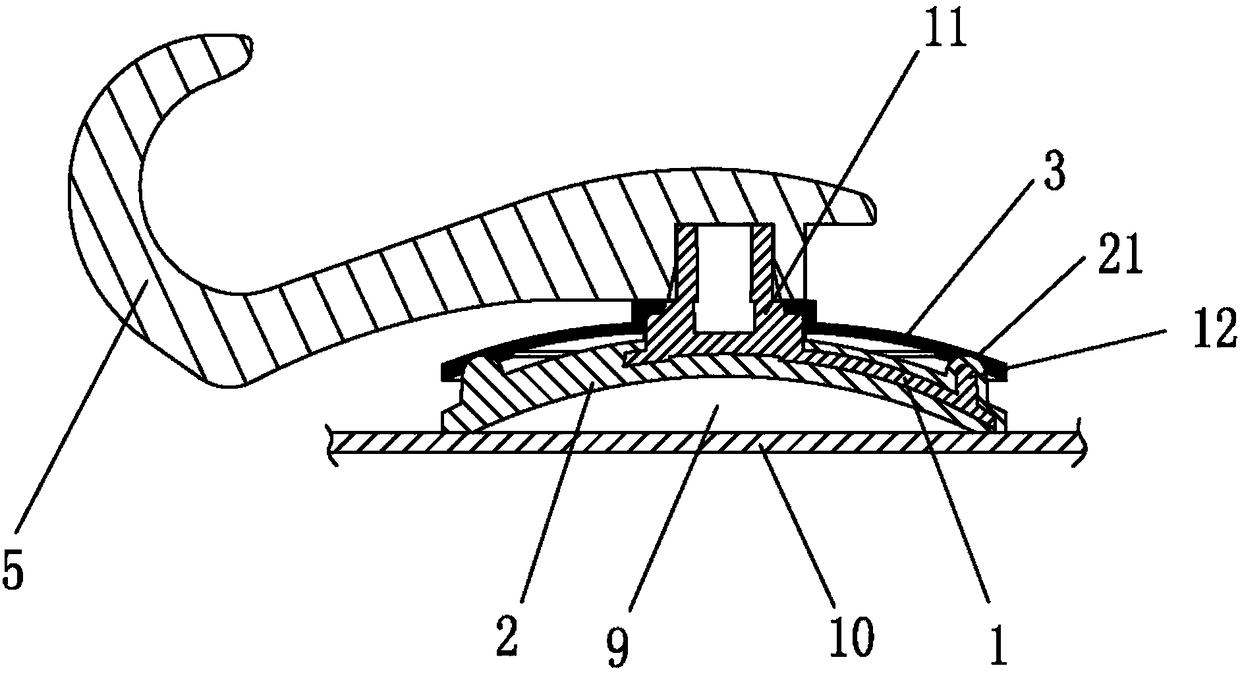
[0024] The suction cup includes elastic colloid 1-1, and the back of the elastic colloid is provided with a connecting piece 1-6. There is a pressing piece 1-7 which is connected with the connecting piece 1-6 and presses the elastic colloid 1-1 to realize connection and fixing.

[0025] When in use, put the suction cup on the base surface 1-8, the bottom surface of the elastic colloid 1-1 is attached to the base surface 1-8, and then press the ...


PUM


Abstract

The invention discloses a suction cup pressing plate, in particular to a suction cup pressing plate used in a suction cup for providing bounce. The suction cup pressing plate comprises a curved surface pressing plate body and a positioning table. The positioning table is located at the middle portion of the suction cup pressing plate. A planar center face is arranged between the positioning table and the curved surface pressing plate body. The positioning table, the curved surface pressing plate body and the center face are integrally formed. The above center face is in a horizontal planar shape, the curved surface pressing plate body is in an arc face, and a folding line is arranged between the center face and the curved surface pressing plate body. The annular radius of the center face of the suction cup pressing plate is R2-R1, wherein R2 is the distance between the leftmost end of the center face and the center of the positioning table, R1 is the radius of the positioning table, and R2-R1 is larger than 0 mm and smaller than or equal to 5 mm. According to the purpose of the suction cup pressing plate, the problem that the bounce of a suction cup cover in the prior art is too small or too large is solved, and a suction cup cover with the proper bounce is provided.

Description

【Technical field】 [0001] The invention relates to a sucker pressing plate, which is used in a sucker to provide rebound force. 【Background technique】 [0002] The applicant has applied for a utility model patent named "a new type of suction cup", the application number is 201320107296.8, the announcement number is 203214561U, and the application date is 2013-03-08. [0003] The suction cup (see image 3 ), including a skeleton 1, the back of the skeleton 1 is provided with a connecting rod 11 and an annular rib 12, the skeleton 1 is covered with elastic colloid 2, and the elastic colloid 2 is wrapped at the rib 12 A convex ring 21 is formed on the cover, and a suction cup cover 3 is sleeved on the connecting rod 11. The back of the suction cup cover 3 is connected with a connecting piece 5 that is connected with the connecting rod 11 and pulls and compresses the skeleton 1 to realize connection and fixing. The ribs 12 are pressed against the bottom surface of the suction cu...

Claims


Application Information

Patent Timeline
Patent Type & Authority Patents(China)
IPC IPC(8): F16B47/00
CPCF16B47/00
Inventor 石正兵
Owner ZHONGSHAN TAILI HOUSEHOLD PROD MFG
Why Eureka
Try Eureka