Combined air valve

An air valve, combined technology, applied in the valve details, valve device, functional valve type and other directions, can solve the problems of complicated operation, air valve closing water hammer, exhaustion and other problems, achieve simple operation and save manpower The effect of physical strength and life extension

Inactive Publication Date: 2016-12-07
WUHAN DAYU VALVE
View PDF7 Cites 3 Cited by
  • Summary
  • Abstract
  • Description
  • Claims
  • Application Information

AI Technical Summary

Problems solved by technology

However, its closing parts are easy to be held hostage by the high-speed airflow during the high-speed exhaust process and suddenly block the exhaust orifice to cause blowing or air blocking. In the closed state, even if the pipeline is full of gas that needs to be discharged, the exhaust will not be opened again, and when the blowing blockage occurs, it will cause the water hammer of the air valve to close the valve
[0004] 2. The composite exhaust valve (air valve), which adds a micro exhaust valve (air valve) on the basis of the direct action or float-operated high-speed intake and exhaust valve (air valve), although it can be used when the system is full and There is a small amount of exhaust under pressure, but the exhaust is not exhausted, it cannot be exhausted immediately, the exhaust is sprayed with water at the same time, the seal is not tight, and the water hammer of cavity bridging and valve closing cannot be suppressed
However, the structure is relatively complex, and the operation is also relatively cumbersome. In actual operation, it is necessary to judge whether the gas in the valve cavity needs to be discharged, and manual operation is relatively difficult.

Method used


Image

  • Combined air valve
  • Combined air valve
  • Combined air valve

Examples


Embodiment Construction

[0032] The present invention will be further described in detail below in conjunction with the accompanying drawings and specific embodiments.

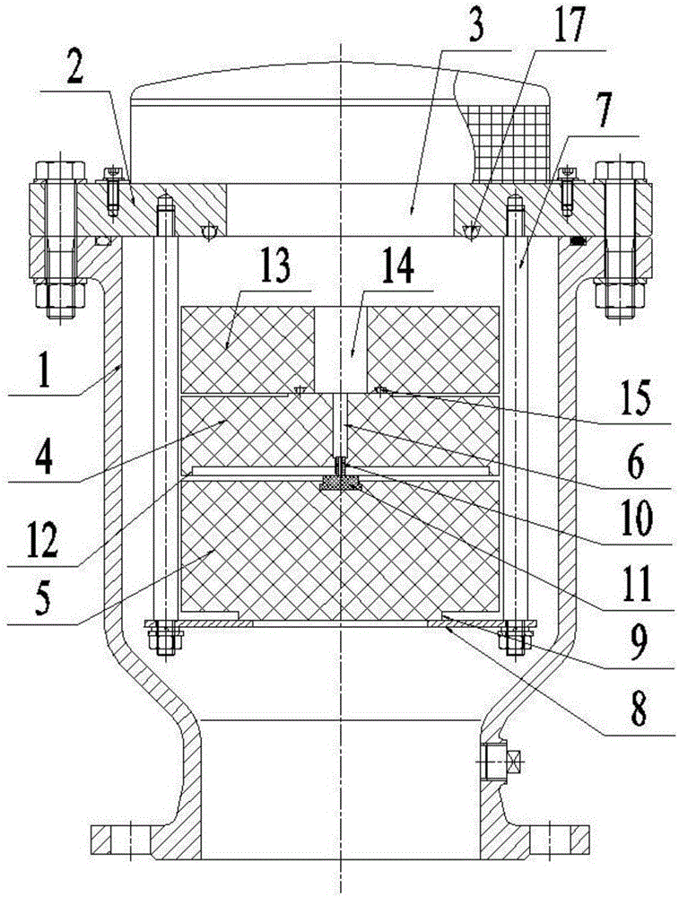
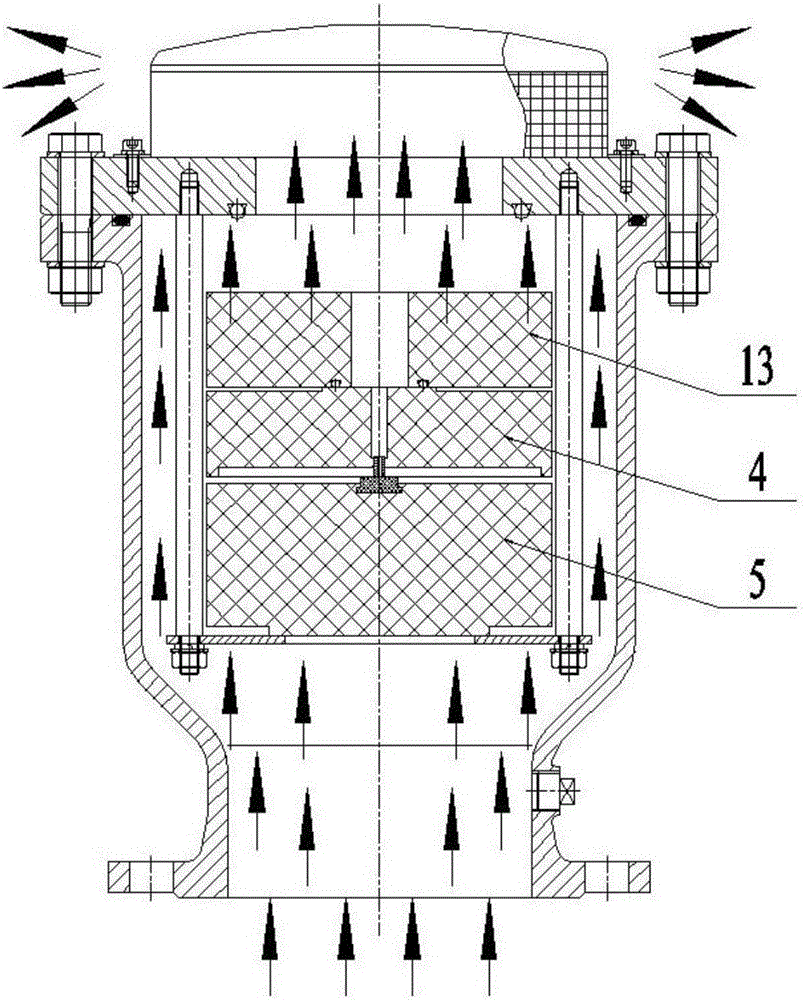
[0033] Such as Figure 1~2 , a combined air valve, including a valve body 1 and a valve cover 2, the lower end of the valve body 1 communicates with the pipe body that conveys the flow medium (water in this embodiment), and the valve cover 2 is fixed on the upper end of the valve body 1 and connected with the The valve cover 2 is provided with a discharge port 3 for discharging gas, and a large amount of gas is discharged from the discharge port 3 to avoid gathering in the pipeline and affecting the transportation of the fluid medium.

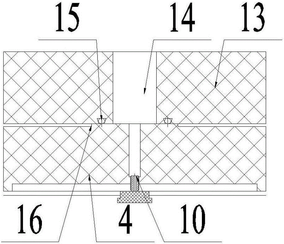
[0034] In this embodiment, the exhaust function is realized by the upper floating body 4 and the lower floating body 5. Both the upper floating body 4 and the lower floating body 5 are made of a material whose density is lower than that of water, and the upper floating body 4 and the lower floating bod...


PUM


Abstract

The invention relates to the technical field of pipeline valves and particularly relates to a combined air valve comprising a valve body and a valve cover; an exhaust port is formed in the valve cover, and an upper floating body and a lower floating body which are overlaid up and down and of which the densities are smaller than the density of a fluid are arranged in a valve cavity of the valve body; a guide device is mounted on the valve cover; the upper floating body and the lower floating body can be arranged in the valve cavity in a way of vertically moving up and down through the limitation of the guide device, gas exhaust gaps are remained between the upper floating body and the inner wall of the valve body and between the lower floating body and the inner wall of the valve body, and an exhaust microchannel communicating with the exhaust port is formed in the upper floating body; the lower end of the exhaust microchannel is connected with the upper end surface of the lower floating body in a sealing way when the upper floating body and the lower floating body are connected together; and the lower end of the exhaust microchannel communicates with the gaps between the floating bodies and the inner wall of the valve body when the upper floating body and the lower floating body are disconnected. The combined air valve is simple in structure, convenient to mount, free of artificial unattendance, capable of rapidly and safely exhausting gases in a pipeline and prolonging the service life of a main structure of the pipeline and extremely high in popularization value.

Description

technical field [0001] The invention relates to the technical field of pipeline valves, in particular to a combined air valve. Background technique [0002] In long-distance water pipelines, the accumulated gas in the pipeline will reduce the efficiency of pipeline water filling and even make it difficult to complete it smoothly. Therefore, high-speed intake and exhaust valves (air valves) need to be used to remove the gas in the pipeline when filling the pipeline. At present, there are two structures of the existing exhaust air valve: [0003] 1. Direct-action or float-operated high-speed intake and exhaust valves (air valves), which automatically exhaust a large amount of air when the empty pipe is filled with water or automatically inhale a large amount of air when the pipeline system is emptied; when the system is full and under pressure, it will Stay off and never turn on again. However, its closing parts are easy to be held hostage by the high-speed airflow during th...

Claims


Application Information

Patent Timeline
Patent Type & Authority Applications(China)
IPC IPC(8): F16K24/04F16K31/20F16K47/02
CPCF16K24/044F16K31/20F16K47/023
Inventor 李习洪詹小华
Owner WUHAN DAYU VALVE
Why Eureka
Try Eureka