Pressure sensor

A pressure sensor and sensor body technology, applied in the direction of displaying the liquid level indicator through pressure measurement, can solve the problems of inconvenient plugging and unplugging, damage to the electrical panel or frame, etc., to achieve convenient and efficient replacement of the pressure sensor, firm fixation, The effect of reducing the size

Active Publication Date: 2016-12-07
ILLINOIS TOOL WORKS INC
View PDF8 Cites 5 Cited by
  • Summary
  • Abstract
  • Description
  • Claims
  • Application Information

AI Technical Summary

Problems solved by technology

Many buckle structures are plug-in buckles. The plastic buckle is inserted into the hole of the panel and snapped into it to fix the pressure sensor. Once the pressure sensor needs to be replaced, the buckle cannot be easily removed and can only be disassembled by violence. Risk of damage to electrical panel or frame

Method used


Image

  • Pressure sensor
  • Pressure sensor
  • Pressure sensor

Examples


Embodiment Construction

[0042] Various embodiments of the invention will be described below with reference to the accompanying drawings, which form a part hereof. It should be understood that although directional terms such as "front", "rear", "upper", "lower", "left", "right", etc. are used herein to describe various exemplary structural parts of the invention and elements, but these terms are used herein for explanatory purposes only, based on the example orientations shown in the figures. Since the disclosed embodiments of the present invention may be arranged in different orientations, these directional terms are for illustration only and should not be viewed as limiting. Where possible, the same or similar reference numerals used in the present invention refer to the same components.

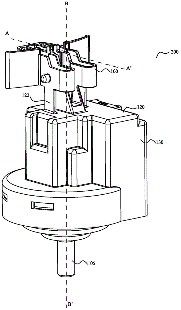
[0043] figure 1 It is a perspective view of the structure of the pressure sensor 200 of the present invention.

[0044] Such as figure 1 As shown, the pressure sensor 200 includes a pressure sensor body and a ...


PUM


Abstract

A pressure sensor comprises a pressure sensor body, wherein the pressure sensor body comprises a casing and a buckle, wherein a hydraulically sensitive deformable membrane is accommodated in the casing; the buckle is arranged at the top of the casing, buckle bodies and buckle wings are arranged on the buckle, and the buckle is detachably buckled and fixed with an electric appliance fixing rack. A first clamping foot and a second clamping foot on an elastic first arm and an elastic second arm are extruded and inserted into a hole of an electric appliance panel by means of the buckle and are firmly fixed through a first clamping wing and a second clamping wing on the outer side of the hole, so that the pressure sensor can be tightly hung on the panel and is convenient to mount and firmly fixed. The buckle can be pinched and extruded from outer sides of the first arm and the second arm and can be taken out of the hole of the panel when the width of the first clamping foot and the second clamping foot is smaller than the hole of the panel, and the pressure sensor is convenient and efficient to replace.

Description

technical field [0001] The invention relates to a pressure sensor, in particular to a pressure sensor connected to a water pool or a water collection box of a household appliance in use and used for detecting the water level of the water box. Background technique [0002] The present invention relates to an improved pressure sensor or pressure switch for detecting an operating parameter of a household appliance featuring a part that is movable relative to the carcass of the appliance itself, such as a washing machine, dryer or the like. Cylinder or pool of type machine. [0003] French patent application FR-A-2767194 describes a system for detecting some of these parameters using a liquid that is connected to the water supply system of the household appliance and integrally connected to the rotating basket containing the household appliance (washing machine or dryer). A pressure switch (pressure sensor) for closing the cylinder; it is known that the cylinder is connected to...

Claims


Application Information

Patent Timeline
Patent Type & Authority Applications(China)
IPC IPC(8): G01F23/16
Inventor 赖勇
Owner ILLINOIS TOOL WORKS INC
Why Eureka
Try Eureka