
Auxiliary jig for withstand voltage tester

A technology of withstand voltage tester and jig, which is applied in the direction of testing dielectric strength, components and instruments of electrical measuring instruments, etc., can solve the problems of increasing test time, potential safety hazards, unfavorable operation, etc., and achieves reduction of test steps, Guaranteed convenience and convenient clamping effect

Pending Publication Date: 2016-12-07
安徽汇展热交换系统股份有限公司
View PDF7 Cites 4 Cited by
  • Summary
  • Abstract
  • Description
  • Claims
  • Application Information

AI Technical Summary

Problems solved by technology

The existing test method is limited by conditions. The crocodile clip of the test instrument is not completely clamped by the contact conductive block, and it is likely to slip off, which poses a safety hazard; when the product is tested, the product must be taken out for testing and then put in, which greatly increases the testing time. Time is not conducive to operation; when the product is tested, there is no insulation material around it, and there are too many exposed parts, which means that there are more chances of contact with people.

Method used


Image

  • Auxiliary jig for withstand voltage tester

Examples


Embodiment Construction

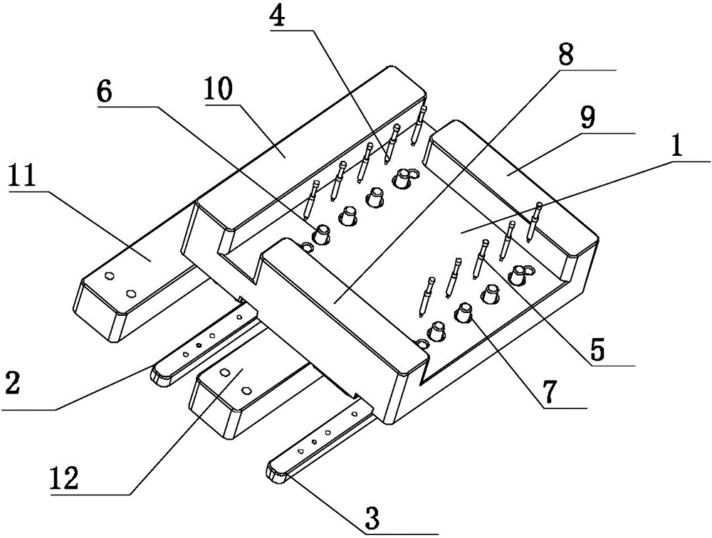
[0013] refer to figure 1 , the present invention proposes an auxiliary fixture for a withstand voltage tester, including a placement plate 1, a first conductive plate 2, a second conductive plate 3, five first current probes 4, five second current probes 5, five A first conductive cap 6, five second conductive caps 7, a first riser 11 and a second riser 12, wherein:

[0014] The first conductive plate 2 and the second conductive plate 3 are respectively connected to the placing plate 1 and located on the same side of the placing plate 1 , and the first conductive plate 2 and the second conductive plate 3 are arranged in parallel.

[0015] Five first current probes 4 are arranged at intervals along the extending direction of the first conductive plate 2, and one end of the five first current probes 4 respectively passes through the placement plate 1 and is connected to the first conductive plate 2, specifically: the first conductive plate 2 There are first card slots whose num...


PUM


Abstract

The invention provides an auxiliary jig for a withstand voltage tester. The auxiliary jig comprises a placing plate, a first current-conducting plate, a second current-conducting plate, a plurality of first current probes, a plurality of second current probes, a plurality of first conductive caps, and a plurality of second conductive caps. The plurality of first current probes are arranged at intervals along the extension direction of the first current-conducting plate. One ends of the plurality of first current probes respectively penetrate through the placing plate to extend into the first current-conducting plate. The number of the first current probes is the same as the number of the first conductive caps. One end of each first current probe, located in the placing plate, is respectively connected with the corresponding first conductive cap. The plurality of second current probes are arranged at intervals along the extension direction of the second current-conducting plate. One ends of the plurality of second current probes respectively penetrate through the placing plate to extend into the second current-conducting plate. The number of the second current probes is the same as the number of the second conductive caps. One end of each second current probe, located in the placing plate, is respectively connected with the corresponding second conductive cap. The auxiliary jig is matched with a clamp for clamping products. By means of the auxiliary jig, users are convenient to take and place products. Meanwhile, test steps are reduced, and the test convenience is guaranteed.

Description

technical field [0001] The invention relates to the technical field of withstand voltage insulation and impulse current testing, in particular to an auxiliary fixture for a withstand voltage tester. Background technique [0002] The withstand voltage insulation and impulse current test is one of the necessary tests for product shipment, and it is an important standard to measure whether the product is qualified; for example, when testing the PB-01 product, it is necessary to take out the combination of each aluminum tube and corrugated strip On the conductive block, it is then connected to a tester for testing; therefore, we designed a fixture that can be quickly tested for these conditions, which greatly improved production efficiency. The existing test method is limited by conditions. The crocodile clip of the test instrument is not completely clamped by the contact conductive block, and it is likely to slip off, posing a safety hazard; when the product is tested, the prod...

Claims


Application Information

Patent Timeline
Patent Type & Authority Applications(China)
IPC IPC(8): G01R1/04G01R31/12
CPCG01R1/0408G01R1/0416G01R31/12
Inventor 陈健
Owner 安徽汇展热交换系统股份有限公司
Learn More