Near-infrared fluorescence microscopic unit imaging device and method based on Hadamard transformation

A technology of Hadamard transform and imaging device, applied in microscopes, measuring devices, optical components, etc., can solve the problems of near-infrared area array detector non-uniformity, inherent spatial noise, and high cost of near-infrared area array detectors.

Inactive Publication Date: 2016-12-07
GUANGDONG UNIV OF TECH
View PDF3 Cites 4 Cited by
  • Summary
  • Abstract
  • Description
  • Claims
  • Application Information

AI Technical Summary

Problems solved by technology

[0004] (1) Due to the late start of the development of near-infrared area detectors in my country, the domestic production process and technology are still immature;
[0005] (2) Near-infrared area detectors involve sensitive national defense and military fields, and there are purchase restrictions abroad;
[0006] (3) The cost of near-infrared area array detectors is very expensive, reaching hundreds of thousands or even millions;
[0007] (4) The near-infrared area detector has non-uniformity problems and inherent spatial noise, which causes distortion and interference to the image
[0008] The above problems greatly limit the further development and application of domestic near-infrared fluorescence microscopy

Method used


Image

  • Near-infrared fluorescence microscopic unit imaging device and method based on Hadamard transformation
  • Near-infrared fluorescence microscopic unit imaging device and method based on Hadamard transformation
  • Near-infrared fluorescence microscopic unit imaging device and method based on Hadamard transformation

Examples


Embodiment 1

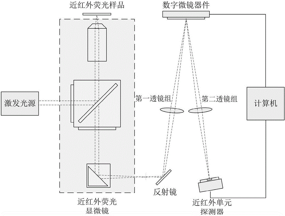
[0045] See attached figure 1 , a near-infrared fluorescence micro-unit imaging device based on Hadamard transform, comprising a near-infrared fluorescence excitation light path, a front imaging light path and a converging light path, the near-infrared fluorescence excitation light path is an excitation light source, a near-infrared fluorescence microscope, and a near-infrared fluorescence excitation path. The fluorescent sample is composed; the front imaging optical path includes a first lens group and a digital micromirror device; the converging optical path includes a second lens group and a near-infrared unit detector.

Embodiment 2

[0047] This embodiment is a further improvement made on the basis of Embodiment 1, see the attached figure 1, the imaging device includes a near-infrared fluorescence excitation light path, a front imaging light path and a converging light path, the near-infrared fluorescence excitation light path is composed of an excitation light source, a near-infrared fluorescence microscope and a near-infrared fluorescence sample; the front imaging light path includes a first lens group, a digital micromirror device; the converging optical path includes a second lens group and a near-infrared unit detector; wherein, the excitation light source is a 660nm LED light source.

Embodiment 3

[0049] This embodiment is a further improvement made on the basis of Embodiment 1, see the attached figure 1 , the imaging device includes a near-infrared fluorescence excitation light path, a front imaging light path and a converging light path, the near-infrared fluorescence excitation light path is composed of an excitation light source, a near-infrared fluorescence microscope and a near-infrared fluorescence sample; the front imaging light path includes a first lens group, a digital micromirror device; the converging optical path includes a second lens group and a near-infrared unit detector, wherein the imaging device also includes a mirror and a computer, and the mirror connects the near-infrared fluorescence excitation optical path and the front imaging In the optical path, the computer connects the digital micromirror device and the near-infrared unit detector.


PUM


Abstract

The invention relates to a near-infrared fluorescence microscopic unit imaging device and method based on Hadamard transformation. The device comprises a near-infrared fluorescence excitation light path, a front imaging light path and a converging light path. A near-infrared fluorescence sample is excited to generate a near-infrared fluorescence microscopic image; a digital microscope device encodes the near-infrared fluorescence microscopic image along the time axis, and single-point imaging is conducted through a near-infrared unit detector; reconstruction of the near-infrared fluorescence microscopic image is realized according to the Hadamard transformation theory. The device and method have the advantages that a mechanical scanning mechanism does not need to be added, expensive near-infrared area-array detector imaging equipment is replaced, and complexity and cost of a near-infrared fluorescence microscopic imaging system are greatly lowered.

Description

technical field [0001] The invention belongs to the field of near-infrared fluorescent microscopic imaging, and in particular relates to a near-infrared fluorescent microscopic unit imaging device and method based on Hadamard transform. Background technique [0002] Fluorescence microscopy imaging technology can detect the internal structure information of fluorescent samples by detecting the spatial fluorescence intensity distribution emitted by fluorescent samples. It has broad application prospects in biomedicine, chemical analysis and other detection fields. Compared with the fluorescence samples whose fluorescence emission spectrum is in the visible region, the fluorescence emission band of the near-infrared fluorescence samples is at Δλ=800-1400nm. The autofluorescence intensity of the sample corresponding to this band Δλ is weak, which can avoid background fluorescence interference and improve the imaging signal-to-noise ratio and detection sensitivity. Fluorescence ...

Claims


Application Information

Patent Timeline
Patent Type & Authority Applications(China)
IPC IPC(8): G06T5/00G06T5/20G01N21/64G02B21/06
CPCG01N21/6458G02B21/06G06T5/002G06T5/10G06T2207/10048
Inventor 白玉磊刘鸿周延周
Owner GUANGDONG UNIV OF TECH
Why Eureka
Try Eureka