Flexible display panel, display device and manufacture method

A flexible display and panel technology, applied in identification devices, printed circuit manufacturing, instruments, etc., can solve problems such as lead-out wire breakage

Active Publication Date: 2016-12-07
BOE TECH GRP CO LTD
View PDF11 Cites 82 Cited by
  • Summary
  • Abstract
  • Description
  • Claims
  • Application Information

AI Technical Summary

Problems solved by technology

[0005] In view of this, the embodiments of the present invention provide a flexible display panel, a display device and a manufacturing method to solve the problem that the lead-out lines of the existing flexible display panel are prone to breakage in the bending area

Method used


Image

  • Flexible display panel, display device and manufacture method
  • Flexible display panel, display device and manufacture method
  • Flexible display panel, display device and manufacture method

Examples


Embodiment Construction

[0028] The specific implementation of the flexible display panel, display device and manufacturing method provided by the embodiments of the present invention will be described in detail below in conjunction with the accompanying drawings.

[0029] The shapes and sizes of the components in the drawings do not reflect the real scale of the flexible display panel, but are only intended to schematically illustrate the content of the present invention.

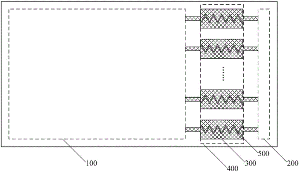
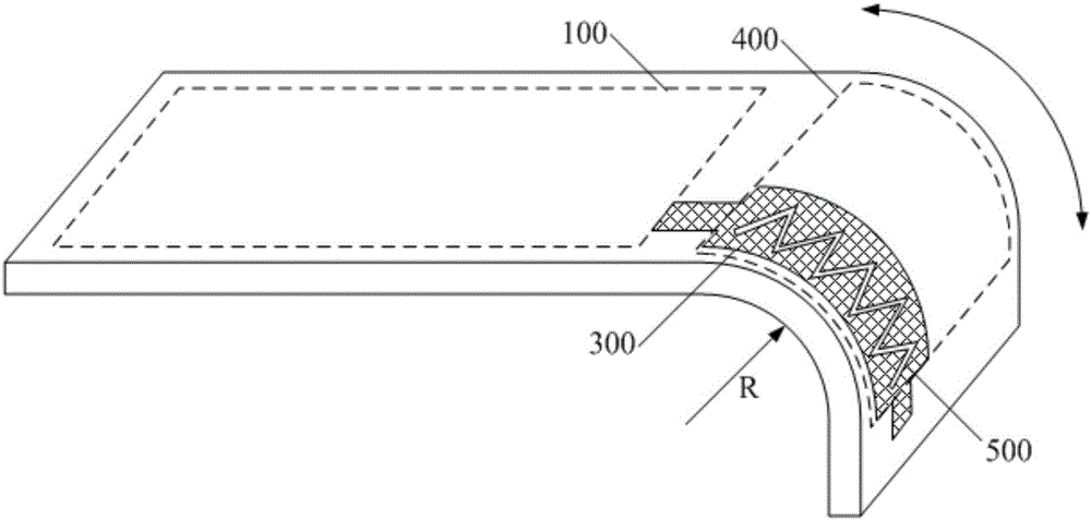
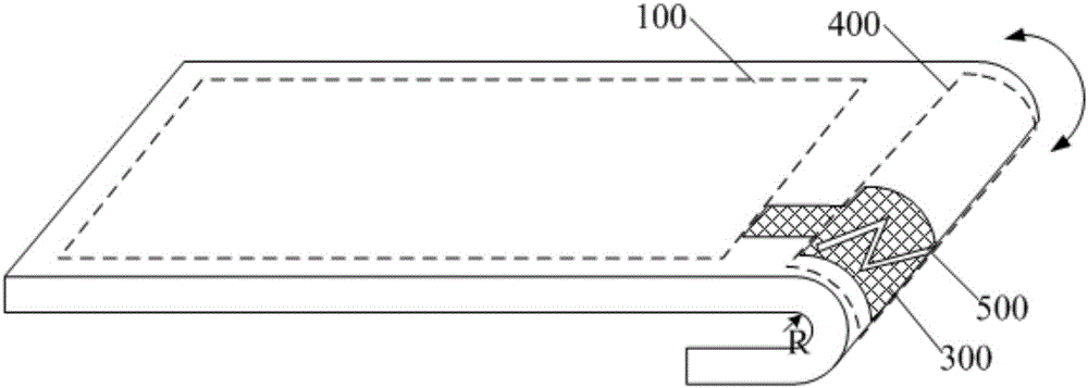
[0030] A flexible display panel provided by an embodiment of the present invention, such as figure 1 As shown, it includes: a plurality of lead-out lines 300 arranged between the display area 100 and the binding area 200, and each lead-out line 300 has a hollow pattern 500 in the bending area 400 between the display area 100 and the binding area 200; Such as Figure 2a with Figure 2b As shown, the flexible display panel is bent toward the rear of the display surface at a set bending radius R in the bending region 400 .

[0031...


PUM

PropertyMeasurementUnit
Line widthaaaaaaaaaa

Abstract

The invention discloses a flexible display panel, a display device and a manufacture method. Hollow patterns are arranged in bent areas, located between a display area and a binding area, of lead wires, so that the bent areas of the lead wires have the new patterns to dredge stress accumulated on the lead wires in the bending process, the lead wires can be helped to release stress when being bent to prevent lead wire breakage, and then the quality and reliability of the flexible display panel can be improved.

Description

technical field [0001] The invention relates to the field of flexible display technology, in particular to a flexible display panel, a display device and a manufacturing method. Background technique [0002] Flexible devices have been widely used in our life. Flexible electronic devices, especially flexible display panels, have attracted more and more attention because of their thinness, bendability, even folding, and good mechanical properties. The flexible display panel is usually made on a flexible carrier. Due to its bending characteristics, it is beneficial to realize the design with narrow borders on all four sides, that is, the side where the flexible display panel is bound with the control chip is bent toward the rear side of the display surface to realize Narrow bezel design in the binding area. Since it is necessary to lead each signal line in the display area to the binding area and then control the signal connection of the chip, multiple lead lines will be set ...

Claims


Application Information

Patent Timeline
IPC IPC(8): G09F9/30
CPCG09F9/301H05K1/118H05K2201/09281H05K2201/0969H05K2201/10128H05K1/028H05K1/189H05K3/303H05K2201/09227
Inventor 石领王本莲刘政
Owner BOE TECH GRP CO LTD
Why Eureka
Try Eureka