Vehicle anti-theft car antenna
A vehicle-mounted antenna and vehicle anti-theft technology, which is applied to the structural connection of antennas, antenna components, and antenna grounding switches, can solve problems such as the failure of anti-theft measures, and achieve the effects of saving internal space, reducing costs, and facilitating concealment
- Summary
- Abstract
- Description
- Claims
- Application Information
AI Technical Summary
Problems solved by technology
Method used
Image
Examples
Embodiment 1
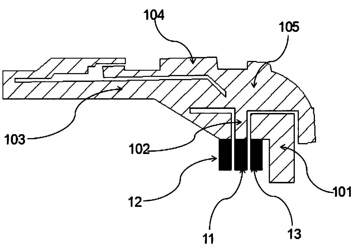
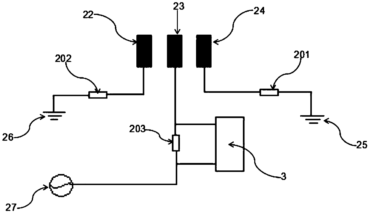
[0022] This embodiment provides a vehicle anti-theft vehicle antenna, including: an antenna unit, a matching circuit unit, and a capacitive sensor chip 3; the capacitive sensor chip 3 is placed in the matching circuit unit, and the antenna unit is connected to the matching circuit unit .
[0023] The antenna unit includes a high frequency trace 104, a low frequency trace 103, a common trace 105, a feed trace 102, a coupling trace 101, a PCB electrical connection ground point 12, a PCB feed point 11 and a PCB ground point 13; The high-frequency trace 104 is placed above the low-frequency trace 103, one end of the common trace 105 is connected to the high-frequency trace 104 and the low-frequency trace 103, and the other end is connected to the feed trace 102 and the PCB electrical connection ground point 12. The electrical wiring 102 is also connected to the PCB feeding point 11 , and the coupling wiring 101 is connected to the PCB grounding point 13 .
[0024] Matching circui...
Embodiment 2
[0027] This embodiment provides another vehicle anti-theft vehicle antenna, including:
[0028] The antenna unit includes a high frequency trace 104, a low frequency trace 103, a common trace 105, a feed trace 102, a coupling trace 101, a PCB electrical connection ground point 12, a PCB feed point 11 and a PCB ground point 13; The high-frequency trace 104 is placed above the low-frequency trace 103, one end of the common trace 105 is connected to the high-frequency trace 104 and the low-frequency trace 103, and the other end is connected to the feed trace 102 and the PCB electrical connection ground point 12. The electrical wiring 102 is also connected to the PCB feeding point 11, and the coupling wiring 101 is connected to the PCB grounding point 13; preferably, the antenna unit is in the form of an IFA antenna;
[0029] Matching circuit unit, including circuit board ground I26, feeding point I22, contact point 23, isolation element capacitor I202, feeding point II24, circuit...
Embodiment 3
[0034] As a supplement to Embodiment 1 or 2: the human body capacitance induction formula: C=ε×A / d, when the relative permittivity ε is determined, the cross-sectional area A between the two metal surfaces of the capacitor and the gap between the two metal surfaces of the capacitor The change of the gap distance d leads to the change of the capacitance C. The human body itself carries current. When the human body is close to the antenna unit, an equivalent capacitance is formed, which will cause the capacitance value on the antenna to change. This change is captured by the capacitive sensor chip 3. , feedback to the MCU side, and issue countermeasures. The antenna feeding mode is pogopin feeding mode or RF line feeding mode.
[0035] The above term circuit board ground means the grounding of the circuit board. The above-mentioned vehicle anti-theft on-board antenna is installed in the on-board equipment. When the on-board equipment is in normal operation, when a human body is ...
PUM
 Abstract
Description
Claims
Application Information
 - R&D
- Intellectual Property
- Life Sciences
- Materials
- Tech Scout
- Unparalleled Data Quality
- Higher Quality Content
- 60% Fewer Hallucinations
Browse by: Latest US Patents, China's latest patents, Technical Efficacy Thesaurus, Application Domain, Technology Topic, Popular Technical Reports.
© 2025 PatSnap. All rights reserved.Legal|Privacy policy|Modern Slavery Act Transparency Statement|Sitemap|About US| Contact US: help@patsnap.com


