
Improved droop control method and system capable of suppressing ring current in direct-current micro-grid

A technology of DC microgrid and control method, applied in the field of DC microgrid, can solve the problems of unfavorable busbar voltage, increased converter loss, non-negligible line resistance, etc., and achieves the effects of accurate distribution, maintenance of busbar voltage, and suppression of circulating current.

Active Publication Date: 2016-12-07
FOSHAN POWER SUPPLY BUREAU GUANGDONG POWER GRID
View PDF2 Cites 10 Cited by
  • Summary
  • Abstract
  • Description
  • Claims
  • Application Information

AI Technical Summary

Problems solved by technology

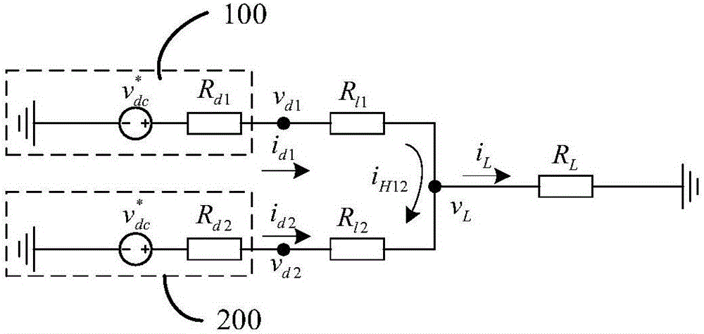
[0002] In the DC micro-grid, each micro-source is connected to the DC bus through the corresponding converter. When the output voltage of the converter is not equal, a circulating current will be generated, which will increase the loss of the converter; the line resistance from each micro-source to the load is not equal. , will lead to inaccurate load power distribution; voltage drop across line resistance will deteriorate bus voltage quality
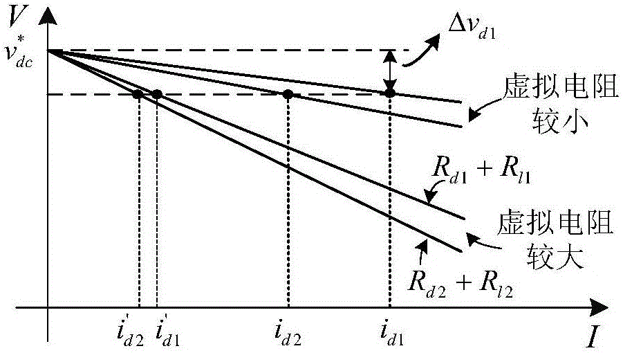
In view of the above problems, the droop control method based on fixed virtual resistance is currently used. When the cable resistance is negligible (such as in a small microgrid), the load power distribution can be made accurately by selecting an appropriate and fixed virtual resistance, while in the microgrid scale When the line resistance is large, the line resistance cannot be ignored, and the traditional droop control method based on fixed virtual resistance is difficult to meet the dual goals of accurate load power distribution and suppression of circulating current
In addition, the traditional droop control has the contradiction between accurately distributing load power and stabilizing the DC bus voltage, which is not conducive to the stability of the bus voltage

Method used


Image

  • Improved droop control method and system capable of suppressing ring current in direct-current micro-grid
  • Improved droop control method and system capable of suppressing ring current in direct-current micro-grid
  • Improved droop control method and system capable of suppressing ring current in direct-current micro-grid

Examples


Embodiment Construction

[0030] The content of the present invention will be further described in detail below in conjunction with preferred embodiments and accompanying drawings. Apparently, the embodiments described below are only used to explain the present invention, not to limit the present invention. Based on the embodiments of the present invention, all other embodiments obtained by persons of ordinary skill in the art without making creative efforts belong to the protection scope of the present invention. It should be understood that although the terms "first", "second", etc. are used hereinafter to describe various information, these information should not be limited to these terms, and these terms are only used to distinguish information of the same type from each other. For example, "first" information may also be referred to as "second" information without departing from the scope of the present invention, and similarly, "second" information may also be referred to as "first" information. ...


PUM


Abstract

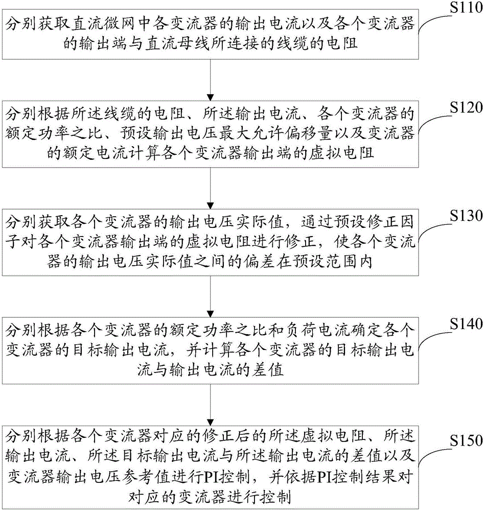
The invention relates to an improved droop control method and system capable of suppressing ring current in a direct-current micro-grid. The method comprises the following steps of: respectively obtaining output current of various current transformers in the direct-current micro-grid and the resistances of the various current transformers and a cable connected with a direct-current bus; respectively calculating virtual resistances of the output ends of the various current transformers; correcting the virtual resistances of the output ends of the various current transformers through a pre-set correction factor; calculating a differential value between target output current and output current of the various current transformers; and respectively performing PI control according to the corrected virtual resistances corresponding to the various current transformers, the output current, the differential value between the target output current and the output current, and output voltage reference values of the various current transformers, and controlling the corresponding current transformers according to a PI control result. By means of the improved droop control method and system disclosed by the invention, accurate distribution of load power can be realized; furthermore, the ring current among the current transformers can be effectively suppressed; and thus, the stability of bus voltage can be kept.

Description

technical field [0001] The invention relates to the field of direct current microgrids, in particular to an improved droop control method and system capable of suppressing circulation in a direct current microgrid. Background technique [0002] In the DC micro-grid, each micro-source is connected to the DC bus through the corresponding converter. When the output voltage of the converter is not equal, a circulating current will be generated, which will increase the loss of the converter; the line resistance from each micro-source to the load is not equal. , will lead to inaccurate load power distribution; the voltage drop on the line resistance will deteriorate the bus voltage quality. In view of the above problems, the droop control method based on fixed virtual resistance is currently used. When the cable resistance is negligible (such as in a small microgrid), the load power distribution can be made accurately by selecting an appropriate and fixed virtual resistance, while...

Claims


Application Information

Patent Timeline
Patent Type & Authority Applications(China)
IPC IPC(8): H02J1/00G06F17/12G06F17/15
CPCY02P80/14H02J1/00G06F17/12G06F17/15
Inventor 黄静刘晓华陈道品
Owner FOSHAN POWER SUPPLY BUREAU GUANGDONG POWER GRID
Learn More