PFC power supply device

A technology of power supply device and input power supply, which is applied in the direction of output power conversion device, electrical components, AC power input into DC power output, etc. It can reduce the complexity of the circuit and control difficulty, improve the stability and reliability, and reduce the volume of the filter inductor.

Pending Publication Date: 2018-01-23
XIAN MEGMEET ELECTRICAL CO LTD
View PDF0 Cites 7 Cited by
  • Summary
  • Abstract
  • Description
  • Claims
  • Application Information

AI Technical Summary

Problems solved by technology

[0008] 1) The hardware cannot self-balance the current. It is necessary to sample and control the current of each branch of each phase. The circuit is complicated and the control difficulty increases, which reduces the reliability of the device;
[0009] 2) In the two branches of each interleaved phase, the circulating current is generated due to the different voltages in the interleaved phase. If the circulating current is large, it will affect the working state of the topology, increase the difficulty of control, power tube loss and stress, etc.
Thus reducing the efficiency of the whole machine, the stability and reliability of the system

Method used


Image

  • PFC power supply device
  • PFC power supply device
  • PFC power supply device

Examples


Embodiment Construction

[0038] The structural principle and working principle of the present invention will be further described in detail below in conjunction with the accompanying drawings.

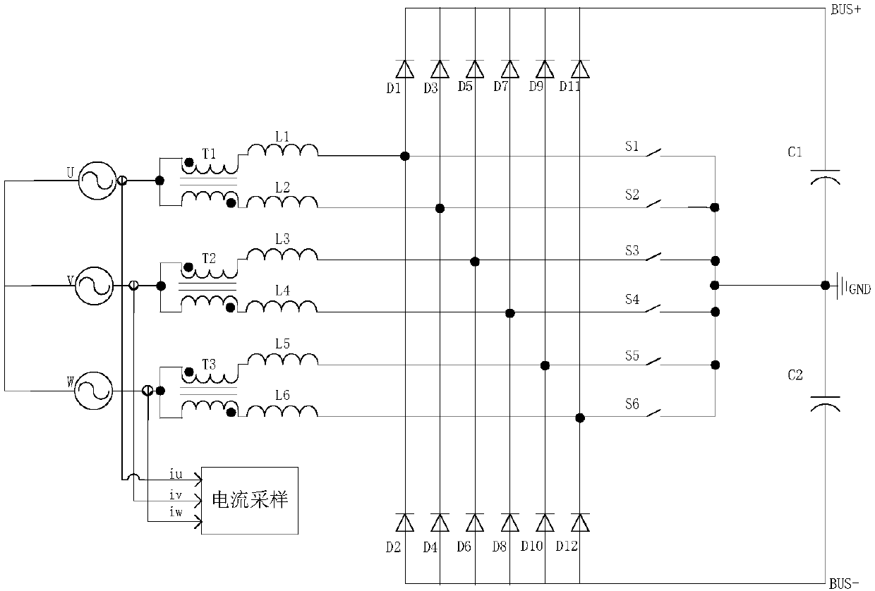
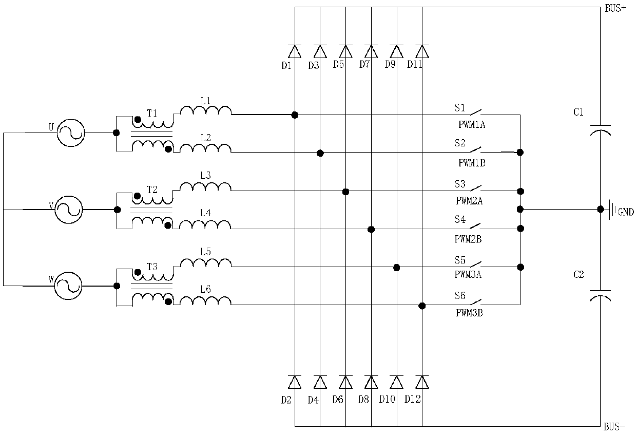
[0039] A PFC power supply device, including an input power supply U, an input power supply V, and an input power supply W; the input power supply U is connected in series with a coupling transformer T1, and the output of the power supply is connected to the input end of the coupling transformer T1; the U phase divides the line through T1 Two circuits, one of the output terminals of T1 is connected in series with the boost inductor L1 and connected to the input terminal of the boost inductor L1, and the other output terminal of T1 is connected in series with the input terminal of the boost inductor L2; the output terminals of the boost inductor L1 are respectively connected to To the anode of the boost diode D1, the cathode of the boost diode D2, and the input terminal of the boost switch S1; the output terminal...


PUM


Abstract

The invention provides a PFC power supply device comprising an input power supply U, an input power supply V and an input power supply W, wherein the input power supply U is connected with a couplingtransformer T1 in series; one path of an output end of T1 is connected with a boost inductor L1 in series and is connected to an input end of the boost inductor L1, the other path of output end of theT1 is connected with the input end of an boost inductor L2; the output end of the boost inductor L1 is respectively connected to the anode of a boost diode D1, the cathode of a boost diode D2 and theinput end of a boost switching tube S1; the boost inductor L2 is respectively connected to the anode of a boost diode D3, the cathode of a boost diode D4 and the input end of a boost switching tube S2; the cathodes of the boost diodes D1and D3 are connected to the anode of a bus capacitor C1, the output ends of the boost switching tubes S1 and S2 are connected to the cathode of the bus capacitorC1, and the anodes of the boost diodes D2 and D4 are connected to the cathode of a bus capacitor C2; the connection modes of the input power supply V and the input power supply W are the same as thoseof the input power supply U; and the PFC power supply device has the advantages of simple control, good stability and reliability, and capability of increasing the impedance in the loop.

Description

technical field [0001] The invention belongs to the technical field of industrial power supply and new energy, and in particular relates to a PFC power supply device. Active power filter, reactive power compensation, power flow control, uninterruptible power supply, AC and DC transmission system, communication power supply, wind power generation, hybrid electric vehicle charging station, industrial frequency converter and other industrial power supply and new energy fields. Background technique [0002] With the rapid development and progress of power electronic technology, power electronic devices play an important role and are widely used in various fields of industry. However, due to the nonlinear characteristics of devices in power electronic devices, voltage and current distortions are caused when energy conversion is performed, and a large number of harmonics are generated. Therefore, many PWM rectifiers with low voltage, current and unity power factor have been propo...

Claims


Application Information

Patent Timeline
Patent Type & Authority Applications(China)
IPC IPC(8): H02M1/44H02M7/219H02M1/14
CPCY02B70/10
Inventor 曹彦哲方飞盛虎张雷刘小刚
Owner XIAN MEGMEET ELECTRICAL CO LTD
Why Eureka
Try Eureka