
Heating unit for warming propane tanks

Inactive Publication Date: 2009-04-30
GREENHEAT IP HLDG LLC
View PDF99 Cites 18 Cited by
  • Summary
  • Abstract
  • Description
  • Claims
  • Application Information

AI Technical Summary

Benefits of technology

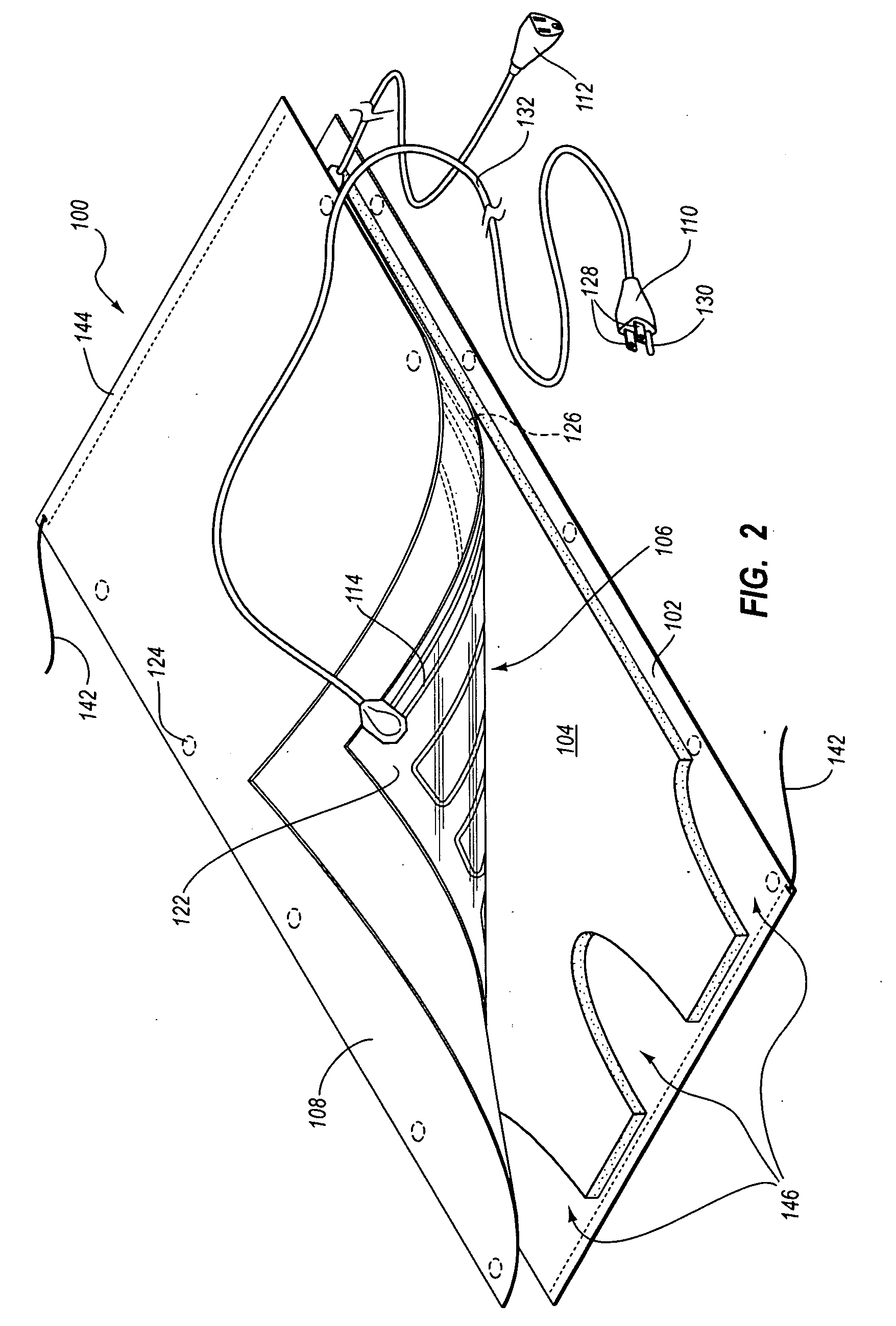
[0005]One embodiment described herein is directed to a heating unit for use in providing evenly distributed heat to a propane tank. The heating unit includes a first pliable cover layer and a second pliable cover layer. A pliable electrical heating element is disposed between the first and the second cover layers. The pliable electrical heating element includes a heat generating element for converting electrical energy to heat energy and a heat spreading element that is attached to the heat generating element. The heat spreading element comprises carbon that is thermally coupled to the heat generating element for distributing the heat energy. A thermal insulation layer is attached to a first side of t

Problems solved by technology

The ability to distribute heat has provided a number of opportunities for increasing human comfort levels for certain activities and has made other activities not previously feasible able to be accomplished.
However, typical warmers only cover a portion of the container's wall.
However, these types of warmers typically result in overheating materials at the location of the warmer while possibly under heating materials in other portions of the container.
This can be a fire hazard depending on the materials used in the warmer, or materials placed near a container being heated.
However, this requires the availability of multiple outlet receptacles and the use of additional power.

Method used


Image

  • Heating unit for warming propane tanks
  • Heating unit for warming propane tanks
  • Heating unit for warming propane tanks

Examples


Embodiment Construction

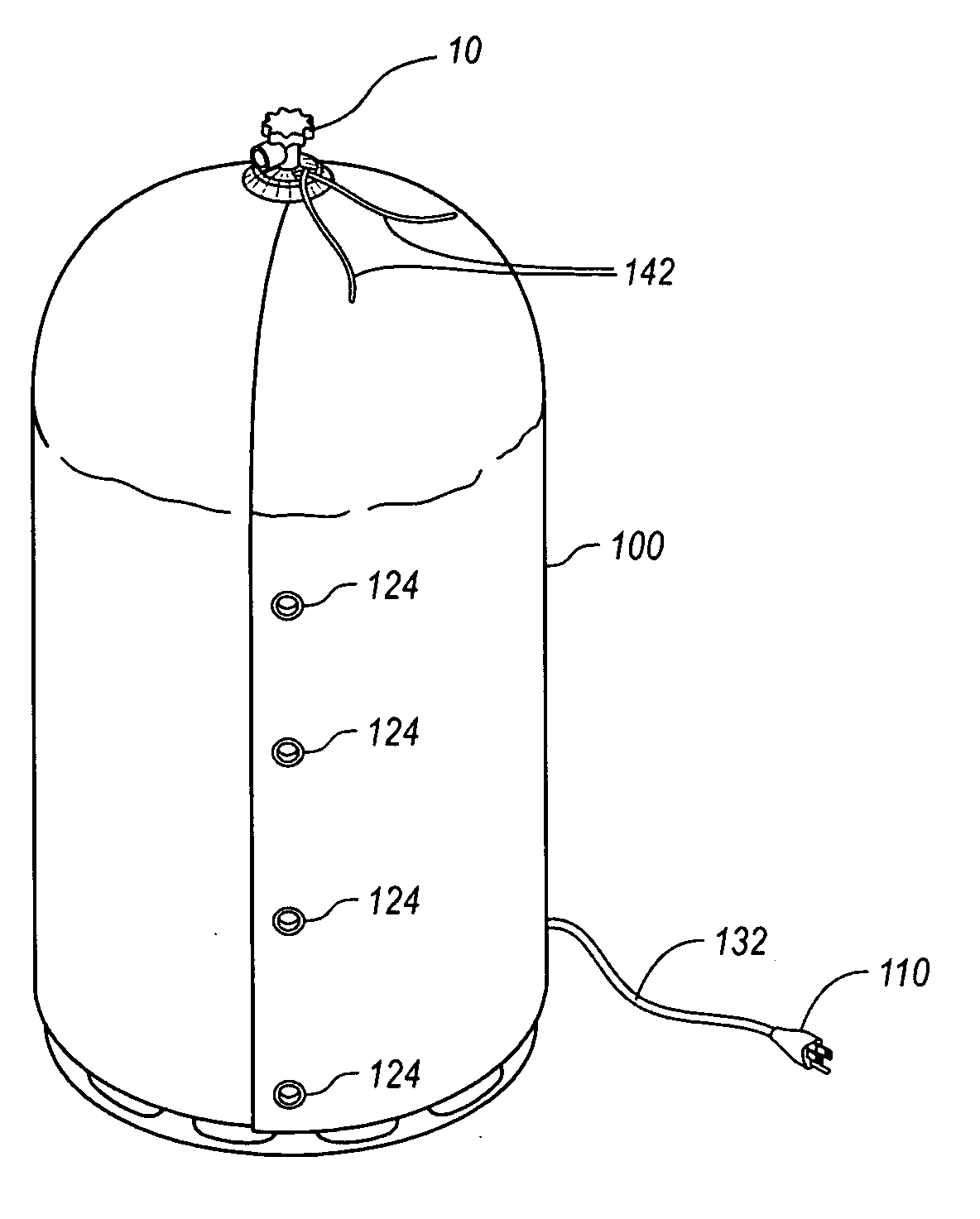
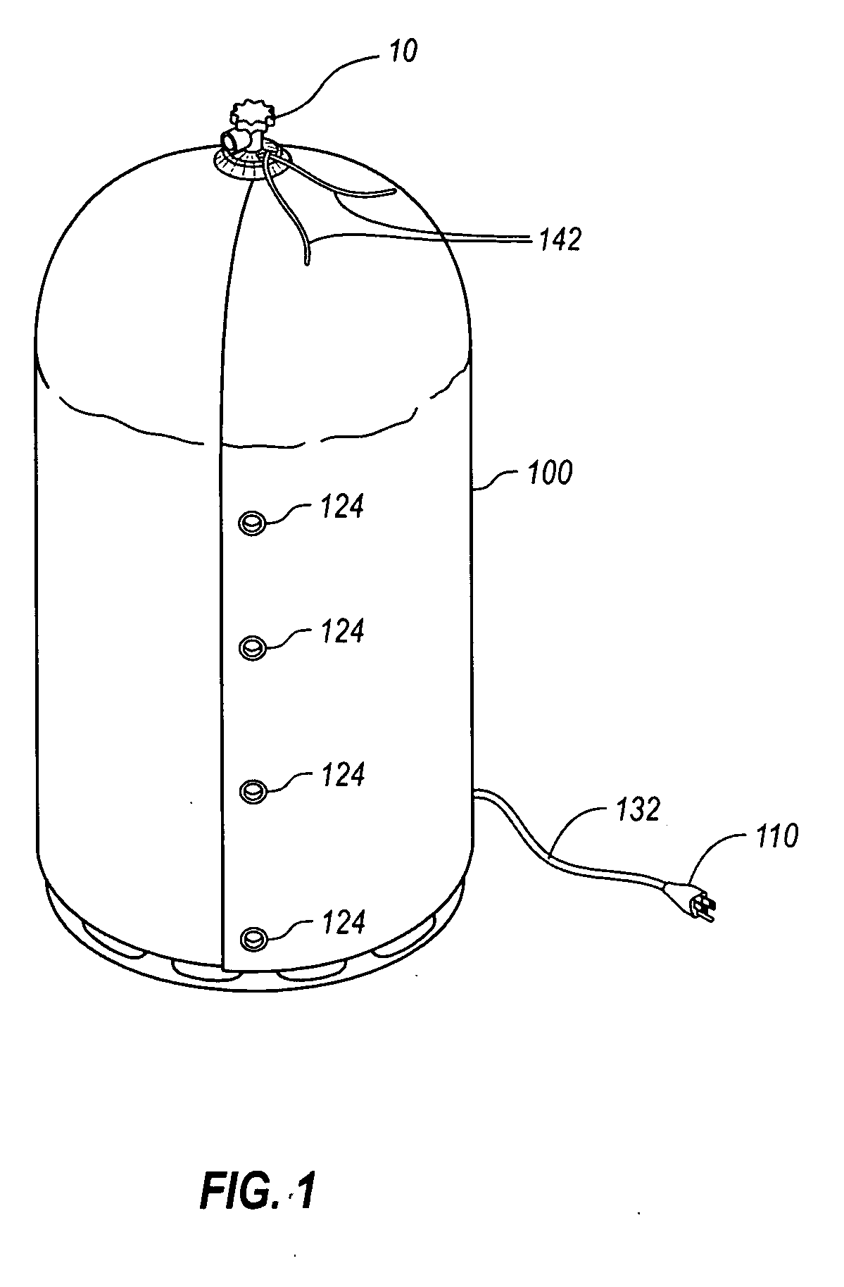
[0015]Disclosed herein are embodiments of a heating unit for use in propane tank warming applications. In particular, embodiments may include a heating unit configured to substantially cover the entire outer surface of a propane tank, including substantially the full circumference and one or both ends of the propane tank. The heating unit includes a heating element which provides heat and spreads the heat over the surface of the heating unit. The heating unit may also include an insulation layer to prevent heat from being lost to an environment external to the propane tank. For example, FIG. 1 illustrates one embodiment of a heating unit configured as a propane tank warmer 100 covering a propane tank 10. While FIG. 1 illustrates the heating unit as a propane tank warmer, it will be appreciated that the heating unit can be sized, shaped, or otherwise configured to provide heat to other types of tanks, buckets, barrel, or similar objects.

[0016]An example of components implemented in o...


PUM

PropertyMeasurementUnit
Temperatureaaaaaaaaaa
Massaaaaaaaaaa

Abstract

A heating unit for use in heating a propane tank is disclosed. The heating unit includes a first pliable cover layer and a second pliable cover layer. A pliable electrical heating element is disposed between the first and the second cover layers. The pliable electrical heating element includes a heat generating element for converting electrical energy to heat energy and a heat spreading element that is attached to the heat generating element. The heat spreading element comprises carbon that is thermally coupled to the heat generating element for distributing the heat energy. A thermal insulation layer is attached to a second side of the pliable electrical heating element and is positioned adjacent the first cover layer. Additionally, a receiving power connector is electrically connected to the heat generating element and is configured to couple to an electrical power source. The heating unit is sized to substantially cover the sides and one or both ends of a propane tank.

Description

CROSS-REFERENCE TO RELATED APPLICATIONS[0001]This application is a continuation in part of co-pending U.S. application Ser. No. 11 / 835,641 filed on Aug. 8, 2007 titled GROUNDED MODULAR HEATED COVER, which is a continuation in part of U.S. patent application Ser. No. 11 / 744,163 filed May 3, 2007, which is a continuation in part of U.S. patent application Ser. No. 11 / 218,156 filed Sep. 1, 2005, now U.S. Pat. No. 7,230,213, issued on Jun. 12, 2007. This application is also a continuation in part of co-pending U.S. application Ser. No. 11 / 422,580 filed on Jun. 6, 2006, titled “A RADIANT HEATING APPARATUS” which claims priority to U.S. Provisional Patent Application 60 / 688,146 filed Jun. 6, 2005, titled LAMINATE HEATING APPARATUS. U.S. application Ser. No. 11 / 422,580 filed on Jun. 6, 2006, titled “A RADIANT HEATING APPARATUS” is a Continuation in Part of U.S. patent application Ser. No. 11 / 218,156, filed Sep. 1, 2005, now U.S. Pat. No. 7,230,213 issued on Jun. 12, 2007, which claims prio...

Claims


Application Information

Patent Timeline
IPC IPC(8): H05B3/34
CPCF24D13/022H05B1/0244Y02B30/26H05B3/565H05B3/56Y02B30/00
Inventor NAYLOR, DAVIDCATERINA, THOMAS
Owner GREENHEAT IP HLDG LLC
Learn More