Liquid-cooled battery pack system

a battery pack and liquid-cooled technology, applied in the field of soft-package battery modules and liquid-cooled battery pack systems, can solve the problems of increasing heat, occupying too much space, and messy internal batteries, and achieves less weld joints, a great increase in the energy density of the battery pack, and a strong practicability

Active Publication Date: 2017-06-08
MICROVAST
View PDF9 Cites 17 Cited by
  • Summary
  • Abstract
  • Description
  • Claims
  • Application Information

AI Technical Summary

Benefits of technology

[0061]Setting flexible connecting bars on the case, fixing the connecting bars' other end to the cover, and the two covers all connected to the case though the flexible connecting bars. When the voltage in the battery case is too large, U-shaped groove cannot completely guarantee the explosion's not occurrence, as to prevent the end plate blowing and hurting people, flexible connecting bars can firmly lock the end plate, even if the battery case explosion the end plate can be guaranteed not to blow and further enhance the safety performance of the battery pack.
[0062]After using the technical solution provided by the present invention, under the circumstance that the materials like electrode sheets, separator and so on are the same, the energy density of the battery pack is greatly increased; the cell and the current collector sheet are fully welded connections, these can cause less weld joints and not easy to produce desoldering, also ensure the stability of the battery cell tabs and high current carrying capacity, and avoid the use of wires when putting the parallel battery modules in series, reducing the volume of the battery pack; immersing with cooling insulating liquid and circulating cooling improve the thermal balance between the cells, the heat distribution in the battery pack is more uniform, the battery pack's insulation property is greatly improved, controlling the heat-dissipation capacity of the system by adjusting the flow rate of the circulating pump, not only the unnecessary energy consumption is avoided, but also the heat-dissipation capacity of the system is increased when needed; cell tab's double cycle design accelerates the heat-dissipation greatly of the high heat occurrence tab area, meanwhile significantly reduces the flow distance of the cooling insulating liquid, makes the cooling more fully and effectively; flow passage design at the bottom of the fixed frame makes the cooling liquid uniformly distribute in the bottom and then makes the flow smooth, and the buffer space is left for the shock suffering from the bottom of the battery pack; setting the rubber seal rings between the fixed frame makes the battery pack completely flexible contact with the outside, this helps preventing shock, and the outside of the cells is sealed to avoid the void bias flow of the cooling liquid.

Problems solved by technology

While electric vehicles have many advantages comparing to conventional cars, but there still are many problems when the lithium-ion battery packs are applied to the electric cars, the most to be resolved is the group technology of the lithium-ion battery, which involves the following key problems: 1. improving the energy density of the battery pack, 2. keeping the battery pack operating with an appropriate temperature range, 3. ensuring the safety performance of the battery pack.
However, the battery module has the following disadvantages: 1. When the battery is in the process of operation, it is easy to lose the welding point between the wires and the current collector sheet while shocking, thereby resulting in pseudo soldering and de-soldering; 2. for there are other wires for sampling such as sampling lines exist, then the adding of the wires, makes the internal battery more messy, and takes up too much space.
Moreover the battery pack uses cylindrical battery cells, the cylindrical battery cells can be welded to the connecting pieces only by spot welding, and because the contact area is small between the poles of the battery cell and the connecting pieces, so this reduces the current through capacity, also increases the heat, and combining such number of cylindrical battery cells into the battery pack, the heat generated will be very great, the design for heat-dissipation will be more complicated, also more energy will be wasted, these further reduce the effective use of the energy in the overall lithium-ion battery pack.
Lithium-ion battery pack generates heat during charging and discharging process, particularly in fast charging or over-discharging process more serious, if the heat is out of control, the consequences is very serious, decomposition of the electrolyte will occur due to the high temperature, the gases produced will fulfill the cell immediately, the cell will burst when the internal pressure of the cell is too high, at last explosion occurred when it contacts the oxygen in the air.
However, since the battery pack is mounted to a group by series and parallel connection, the interval between the battery is small, the battery in the center will have high temperature due to ventilation difficulties, strong wind cools uneven, which causes the decrease in the consistency of the battery, affects the battery life.
If for improving the air cooling effect, increasing the flow passage of the cooling air, it will result in a lot of the waste in volume space, and will reduce the volume energy density of the battery pack system.
So during the usage of lithium-ion batteries of electric vehicles, the air cooling cannot achieve good cooling effects.
However, at present, the design of liquid cooling system is complex, the design of fluid flow passage is not reasonable, heat-dissipation is not at the main heat-dissipation part of the battery pack.
Although also the liquid cooling mode is used, but the actual effect is limited and cannot solve the heat-dissipation problem well.
But after tests it is found that, when the battery packs are used, the heat-generated parts of the individual are characteristic, not the overall heat production are similar, but concentrate on the tab around, the program aims at thermal conductivity on both sides of the battery cell, but the tab portions that the maximum heat produced are few, this cannot fully utilize the advantages of the liquid cooling.
Particularly in extreme cases, the battery after over discharge, or overshoot, the heat capacity produced is great, the prior art technical solution does not solve the heat-dissipation requirements provided under these conditions.

Method used


Image

  • Liquid-cooled battery pack system
  • Liquid-cooled battery pack system
  • Liquid-cooled battery pack system

Examples


example 1

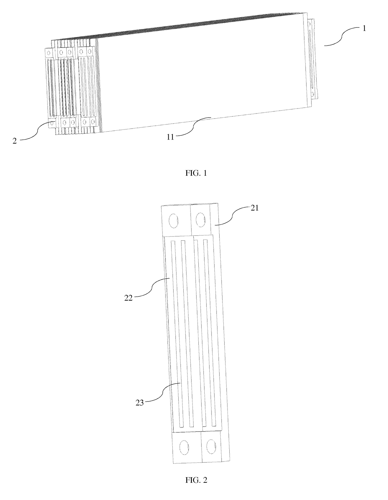
[0075]As shown in FIG. 1 to FIG. 2, the present embodiment provides a cell module 1, comprising a battery cell 11 and a current collector sheet 2, the battery cell 11 is provided with a positive electrode tab and a negative electrode tab, the positive electrode tab and the negative electrode tab are located at the opposite ends of the battery cell 11, the positive electrode tab of the battery cell 11 is a aluminum foil tab, the negative electrode tab is a copper foil tab, the current collector sheet 2 is a combined current collector sheet, the current collector sheet 2 is combined by the aluminum sheet 22 and the copper sheet 21, the aluminum sheet 22 and the copper sheet 21 are fixed by riveting, the aluminum sheet 22 and the copper sheet 21 are respectively provided with a welding groove 23.

[0076]In the process of assembling the battery module 1, the battery cell 11 is connected in parallel first, welding the aluminum foil tab of the battery cell 11 that needs to be connected in p...

example 2

[0078]As shown in FIGS. 1 to 3, the present embodiment provides a cell module 1, comprising a battery cell 11 and a current collector sheet 2, the battery cell 11 is provided with a positive tab and the negative tab, the positive tab and the negative tab are located at the opposite ends of the battery cell 11, the positive tab of the battery cell 11 is a aluminum foil tab, the negative electrode tab is a copper foil tab, the current collector sheet 2 is a combined collector sheet, the current collector sheet is the combination of the aluminum sheet 22 and the copper sheet 21, the aluminum 22 and the copper sheet 21 are fixed by riveting, the aluminum sheet 22 and the copper sheet 21 are respectively provided with the welding grooves 23.

[0079]In the process of assembling the battery module 1, the battery cell 11 is connected in parallel first, welding the aluminum foil tab of the battery cell 11 that needs to be connected in parallel to the welding groove 23 of the aluminum sheet 22,...

example 3

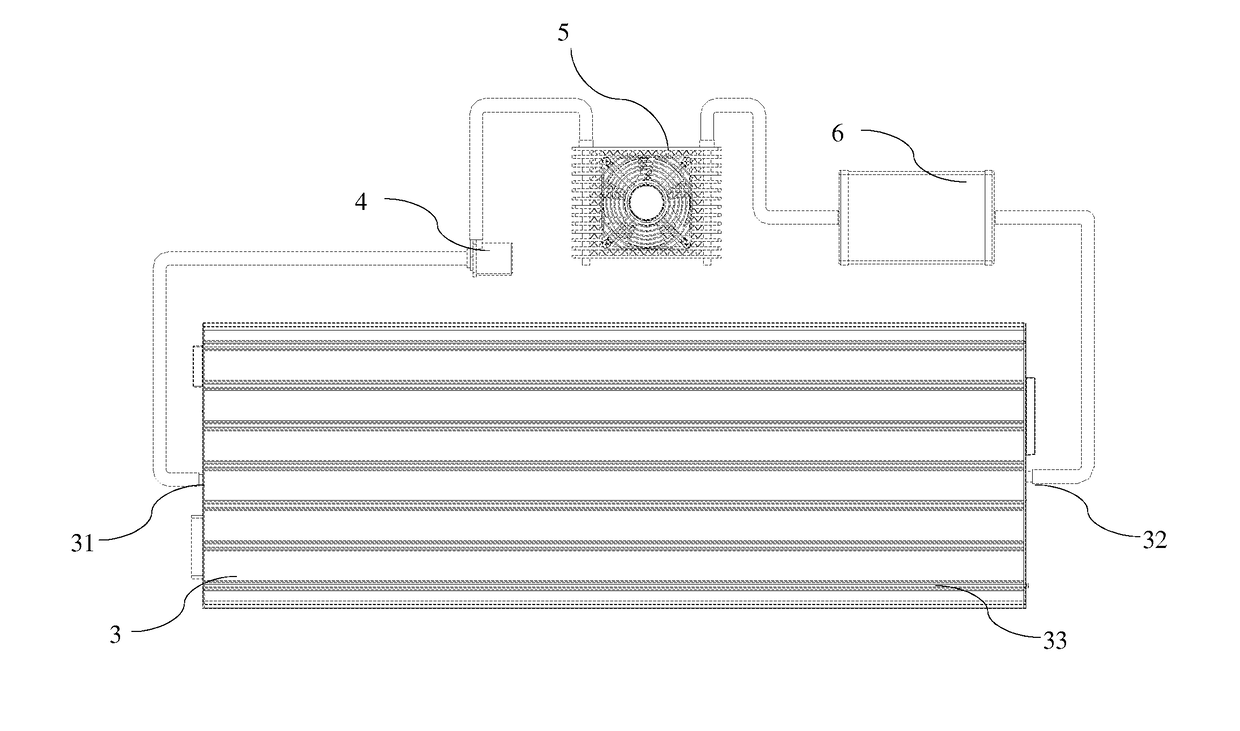
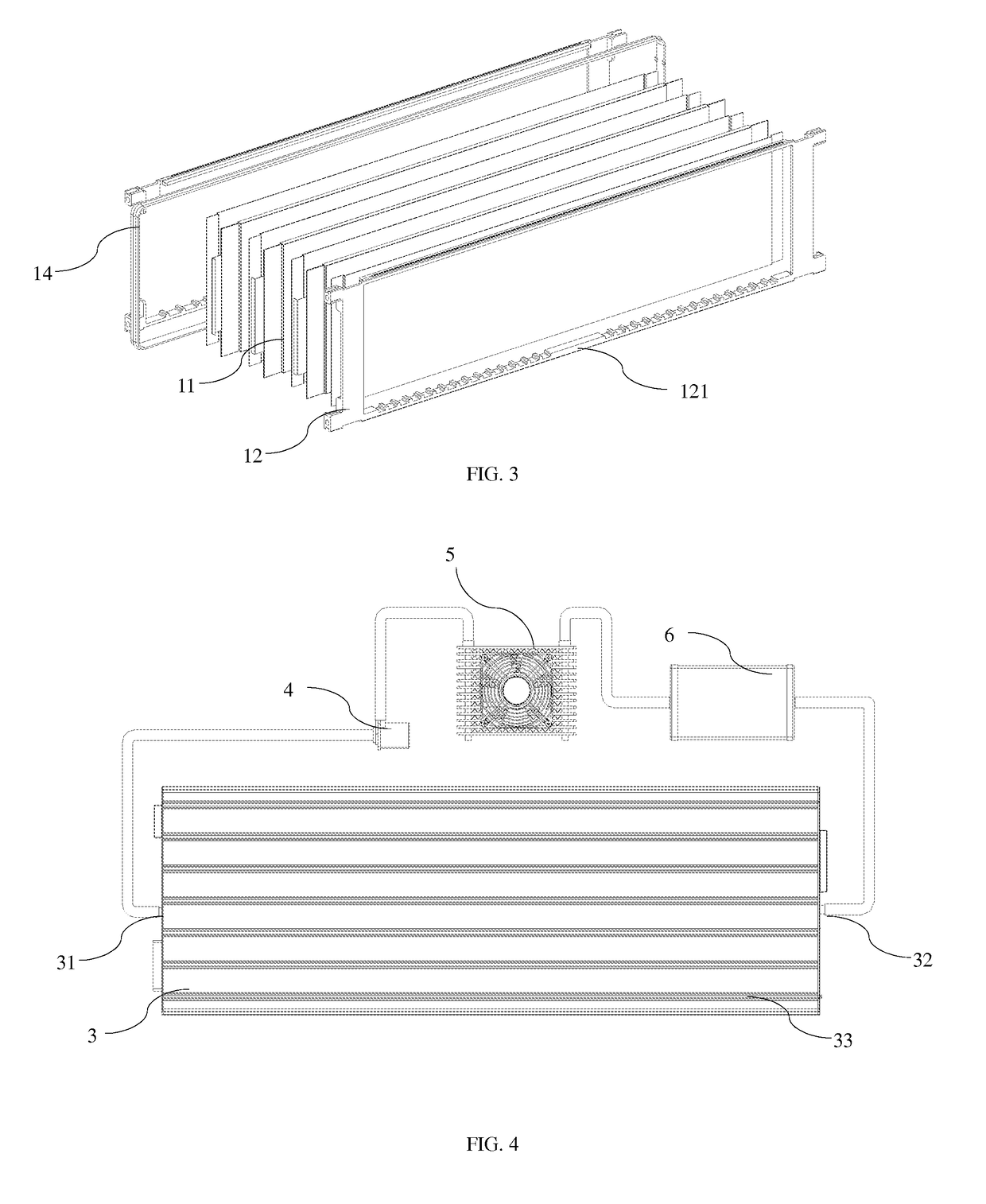
[0082]As shown in FIGS. 1 to 2, FIGS. 4 to 7 and FIG. 11, the present embodiment provides a liquid-cooled battery back system, including a battery module 1, a battery case 3, the cooling insulating liquid, a circulating pump 4, a radiator 5 and a liquid reservoir tank 6, the battery case 3 is sealed by the components of a case 34 with both ends open and a cover 35, a buffer ring 14 and a sealing sheet 16 is set between the case 34 and the cover 35, the battery module 1 and the cooling insulating liquid are disposed in the battery case 3, the battery module 1 is immersed in the cooling insulating liquid, the one end of the battery pack is provided with an outlet of the cooling insulation liquid 32, the other end is provided with an inlet of the cooling insulating liquid 31, the inlet of the cooling insulating liquid 31, the circulating pump 4, the radiator 5, the reservoir tank 6 and the outlet of the cooling insulating liquid 32 are closed connection through pipelines, the outside w...


PUM

PropertyMeasurementUnit
operating temperatureaaaaaaaaaa
volumeaaaaaaaaaa
volumeaaaaaaaaaa

Abstract

The present invention provides a battery module and a liquid-cooled battery system that uses it, a battery cell and a current collector sheet, on the premise that the materials like the electrode and separator and so on are completely the same, energy density of the battery pack is greatly increased; the cell and the current collector sheet are fully welded connections, the joints are fewer and it is not prone to produce desoldering, also ensuring the stability of the of the cell tab and high current carrying capacity, and when putting the parallel battery module in series, the use of wires are avoided, thus reduces the volume of the battery pack; the innovative design for the liquid-cooled battery pack system, improves the thermal balance between the cells, and the heat-dissipation in battery pack distributes more evenly, the insulation property of the battery package is highly improved, controlling the heat-dissipation capacity of the system by adjusting the flow rate of the circulating pump, not only the unnecessary energy consumption can be avoided, but also have a better impact resistance.

Description

CROSS-REFERENCE TO RELATED APPLICATIONS[0001]The present invention claims benefit from China Patent Application, which bears a serial No. CN201410026556.8 and filed on Jan. 21, 2014 and contents of which are hereby incorporated herein by reference.FIELD OF THE INVENTION[0002]This invention relates to a battery module, more specifically relates to a soft-package battery module and a liquid-cooled battery pack system comprising this battery module.BACKGROUND OF THE INVENTION[0003]Lithium-ion battery is a green battery with high energy density, high average output voltage, low self-discharge, no memory effect, wide operating temperature range (is −20° C.-60° C.), excellent cycling performance, high charge-discharge efficiency, long calendar life and that contains non-toxic and hazardous substances. It relies on the lithium-ions' round-trip of embedding and de-embedding between a negative electrode and a positive electrode to complete battery charging and discharging operations.[0004]Wh...

Claims


Application Information

Patent Timeline
Patent Type & Authority Applications(United States)
IPC IPC(8): H01M10/6568H01M10/48H01M10/6557H01M10/613H01M50/211H01M50/224H01M50/242H01M50/244H01M50/249H01M50/509H01M50/516H01M50/533H01M50/581
CPCH01M10/6568H01M10/613H01M10/486H01M2220/20H01M10/6557H01M10/054H01M10/625H01M10/484H01M10/0525Y02E60/10
Inventor DENG, GUOYOUWU, YANGGUO, FENG
Owner MICROVAST
Why Eureka
Try Eureka