Converter circuit based on nine-switch structure

A converter and nine-switch technology, which is applied in the field of converter circuits based on nine-switch structure, can solve the problems of insufficient output levels and bus voltage utilization of nine-switch converters, and achieve good application prospects

Active Publication Date: 2016-12-07
FOSHAN UNIVERSITY
View PDF4 Cites 0 Cited by
  • Summary
  • Abstract
  • Description
  • Claims
  • Application Information

AI Technical Summary

Problems solved by technology

[0005] In view of the shortcomings of the prior art above, the object of the present invention is to provide a converter circuit based on a nin

Method used


Image

  • Converter circuit based on nine-switch structure
  • Converter circuit based on nine-switch structure
  • Converter circuit based on nine-switch structure

Examples


Embodiment Construction

[0026] The invention provides a converter circuit based on a nine-switch structure. In order to make the object, technical solution and effect of the present invention more clear and definite, the present invention will be further described in detail below with reference to the accompanying drawings and examples. It should be understood that the specific embodiments described here are only used to explain the present invention, not to limit the present invention.

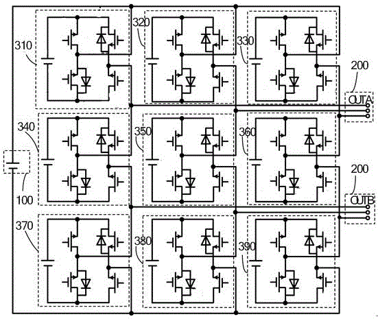
[0027] Such as image 3 Shown is a converter circuit of a specific embodiment of the present invention. It includes: an input power supply 100, an output terminal 200 and nine identical module circuits 310 arranged between the input power supply and the output terminal. The nine module circuits are respectively the first to ninth module circuits (corresponding to image 3 310-390 in).

[0028] The module circuit is used as a power element to replace the power switch tube in the existing nine-switch converter, th...


PUM


Abstract

The invention discloses a converter circuit based on nine-switch structure. The converter circuit includes an input power supply, an output end and 9 same module circuits which are arranged between the input power supply and the output end and serve as power elements. Each module circuit includes a module circuit input power supply, a power circuit and an output port which are successively connected. Along with the changes of the power circuit, each module circuit has at least circuit modals that the voltage of the output port are positive input power supply voltage, inverted input power supply voltage and zero potential. The replacement of the original power switch tube in the converter with the module circuits which have a plurality of circuit modals enables the module circuits to adopt specific control and control the module circuits to enter different circuit modals, and the output of multiple port voltages effectively increases utilization of DC voltage of a busbar and increases output electrical levels.

Description

technical field [0001] The invention relates to the technical field of electric energy conversion equipment, in particular to a converter circuit based on a nine-switch structure. Background technique [0002] figure 1 The nine-switching converter shown, as an indispensable power electronic device in industrial applications, is widely used in power systems, high-speed trains, electric vehicles, large uninterruptible power supplies (UPS), new energy power generation and other fields. However, as the power of the nine-switch converter increases and the switching frequency of the power switch tube increases, the switching loss of the power switch tube increases, which has become a key issue restricting the development of high power density inverters. [0003] In terms of three-phase converter control, compared with the SPWM strategy, the space vector pulse width modulation (SVPWM) technology has a smaller harmonic component of the output current waveform, and a higher utilizat...

Claims


Application Information

Patent Timeline
IPC IPC(8): H02M7/5387H02M7/483
CPCH02M7/483H02M7/5387
Inventor 李湘峰屈莉莉廖慧
Owner FOSHAN UNIVERSITY
Why Eureka
Try Eureka