Repelling drive circuit for H bridge of motor

A drive circuit and drive unit technology, which is applied to the starter of a single DC motor, motor generator/starter, etc., can solve the problems of damaging the H-bridge switch tube, burning out the power supply, and not designing simultaneous conduction of mutually exclusive circuits, etc.

Active Publication Date: 2016-12-07
XUJI GRP +3
View PDF6 Cites 3 Cited by
  • Summary
  • Abstract
  • Description
  • Claims
  • Application Information

AI Technical Summary

Problems solved by technology

[0004] The H-bridge driving circuit can be used to connect with the H-bridge circuit and control the forward and reverse rotation of the motor by driving the H-bridge circuit, but there is no mutual exclusion circuit designed to prevent the simultaneous conduction of the upper and lower bridge arms on the same side of the H-bridge , so when some misoperation or other reasons make the control signals of the upper and lower bridge arms on the same side of the H-bridge circuit valid at the same time, it will cause the switches of the upper and lower bridge arms on the same side to be turned on at the same time, so that the connection from the power supply to the ground is A short circuit is formed, which damages the H-bridge switch tube and even burns out the power supply

Method used


Image

  • Repelling drive circuit for H bridge of motor

Examples


Embodiment Construction

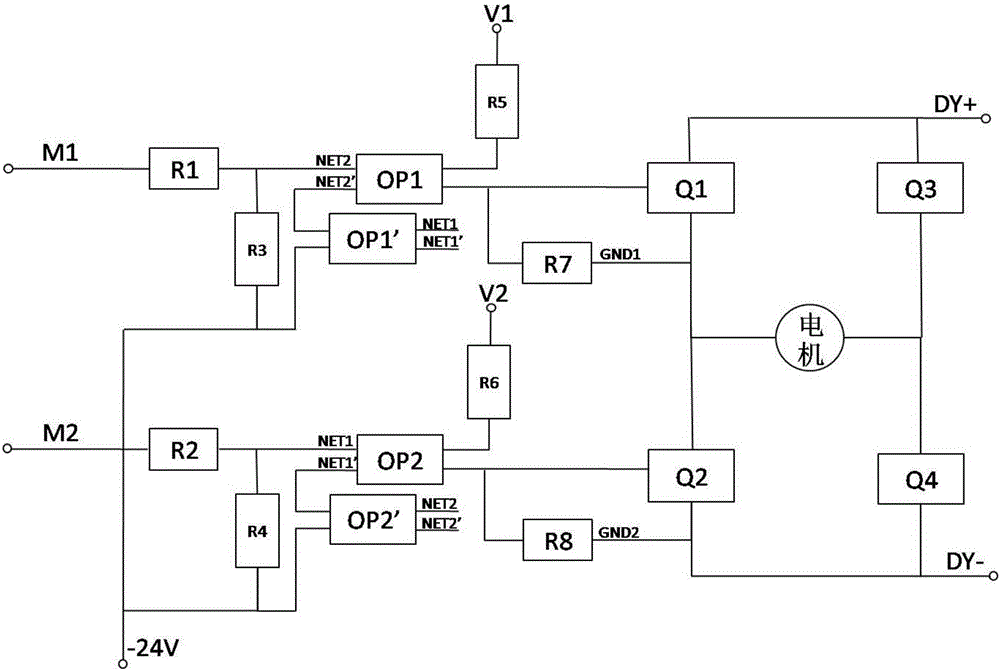
[0015] A mutually exclusive drive circuit for a motor H-bridge, which is used to provide drive signals for switching tubes of two sets of upper and lower bridge arms, and each set of upper and lower bridge arms is correspondingly provided with an upper bridge arm drive unit and a lower bridge arm drive unit The upper bridge arm drive unit includes a first isolation optocoupler, the primary side of the first isolation optocoupler is connected to the upper bridge arm control signal, and the secondary side is connected to the upper bridge arm switch tube; the lower bridge arm drive unit includes a second Two isolated optocouplers OP2, the primary side of the second isolated optocoupler is connected to the control signal of the lower bridge arm, and the secondary side is connected to the switch tube of the lower bridge arm.

[0016] The upper and lower bridge arm drive units also include a first mutual exclusion optocoupler and a second mutual exclusion optocoupler; the primary sid...


PUM


Abstract

The invention relates to a repelling drive circuit for an H bridge of a motor. The repelling drive circuit comprises drive circuits which are connected with four bridge arms of an H bridge circuit respectively, wherein each bridge arm drive circuit comprises an isolating photocoupler for carrying out photoelectric isolation, and a repelling photocoupler for carrying out repelling on the bridge arm drive circuits at the same side of the H bridge; the repelling photocouplers on the same bridge arm are connected with primary sides of the isolating photocouplers in series; and secondary sides of the repelling photocouplers are connected with the primary sides of the isolating photocouplers on different bridge arms at the same side, so that the repelling photocouplers are simultaneously conducted when signals of the isolating photocouplers at the same side of the H bridge are controlled to be simultaneously effective. The secondary sides of the repelling photocouplers are connected with the primary sides of the isolating photocouplers on different bridge arms at the same side and the signals form a passage through the secondary sides of the repelling photocouplers, so that the isolating photocouplers are cut off; and switch tubes of the upper bridge arm and the lower bridge arm at the same side of the H bridge are free of a drive signal to achieve the target of drive repelling of the motor.

Description

technical field [0001] The invention relates to the technical field of motor drive, in particular to a mutually exclusive drive circuit of a motor H bridge. Background technique [0002] When driving a motor, an H-bridge circuit composed of four MOS tubes or power transistors is usually used. If the switch tubes of the upper and lower arms of the motor H-bridge circuit on the same side are turned on at the same time, it is equivalent to a short circuit from the power supply to the ground, and it is likely Cause damage to the triode or MOS tube on the bridge arm of the H bridge, or even burn out the power supply, so it is necessary to ensure that the bridge arms on the same side of the H bridge are not turned on at the same time. [0003] A Chinese utility model patent with the authorized publication number CN 204517703 U discloses a DC motor H-bridge driving circuit. The H-bridge circuit includes two sets of upper and lower bridge arms, that is, the upper and lower bridge ar...

Claims


Application Information

Patent Timeline
Patent Type & Authority Applications(China)
IPC IPC(8): H02P1/22
CPCH02P1/22
Inventor 周俊华姚艳艳王振华陈号陈智杰李莎莎孙世杰江燕良
Owner XUJI GRP
Why Eureka
Try Eureka