
Driving circuit with buffer structure and integrated circuit

A buffer structure and drive circuit technology, applied in electrical components, pulse technology, electronic switches, etc., can solve the problems of power supply short circuit, increased power consumption, and high requirements for gate drive circuits.

Active Publication Date: 2021-02-05
湖南三安半导体有限责任公司
View PDF5 Cites 0 Cited by
  • Summary
  • Abstract
  • Description
  • Claims
  • Application Information

AI Technical Summary

Problems solved by technology

Although gallium nitride devices have many excellent performances, there are still defects in gallium nitride power devices, such as high conversion rate of drain voltage and high drain current conversion rate of gallium nitride power devices, which make the circuit more sensitive to parasitic inductance. , the threshold voltage of gallium nitride power devices is low, and the requirements for gate drive circuits are high
However, since GaN power devices do not have the P-MOS function similar to the traditional Si process, in the gate drive circuit, due to the circuit connection structure of the pull-up transistor and the pull-down transistor, the gate signal of the pull-up transistor is different from the gate signal of the pull-down transistor. There is a delay between signals
When the signal level is converted, due to the delay, the upper and lower tubes may be turned on at the same time, resulting in a short circuit of the power supply, increasing power consumption, and possibly damaging the device in severe cases.

Method used


Image

  • Driving circuit with buffer structure and integrated circuit
  • Driving circuit with buffer structure and integrated circuit
  • Driving circuit with buffer structure and integrated circuit

Examples


Embodiment Construction

[0048] In order to make the purposes, technical solutions and advantages of the embodiments of the present application clearer, the technical solutions in the embodiments of the present application will be clearly and completely described below in conjunction with the drawings in the embodiments of the present application. Obviously, the described embodiments It is a part of the embodiments of this application, not all of them. The components of the embodiments of the application generally described and illustrated in the figures herein may be arranged and designed in a variety of different configurations.

[0049] Accordingly, the following detailed description of the embodiments of the application provided in the accompanying drawings is not intended to limit the scope of the claimed application, but merely represents selected embodiments of the application. Based on the embodiments in this application, all other embodiments obtained by persons of ordinary skill in the art w...


PUM


Abstract

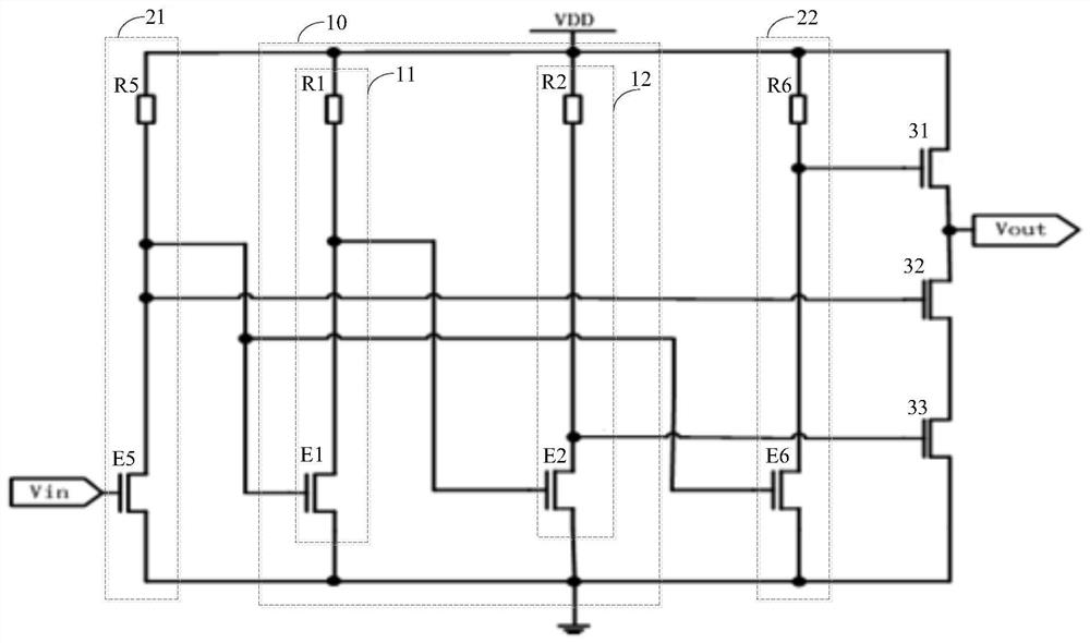
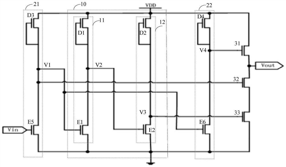
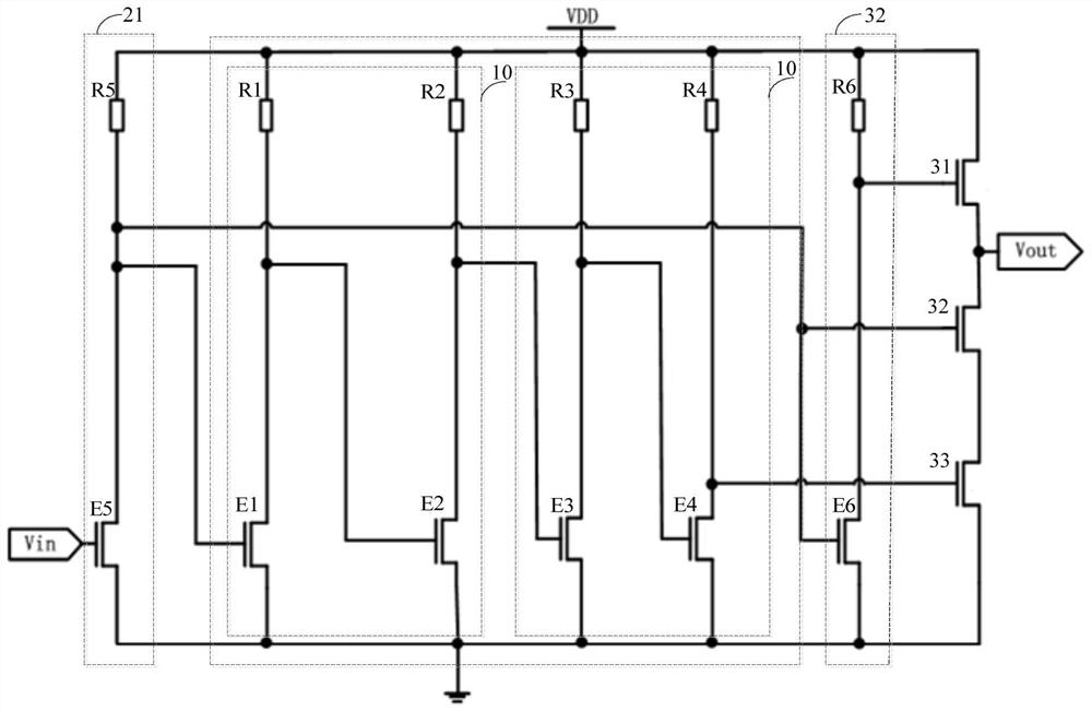
The invention provides a driving circuit with a buffer structure and an integrated circuit; the driving circuit comprises the buffer structure, a first transistor, a second transistor, a third transistor, a first inverter and a second inverter, the output end of the first inverter is connected to the first transistor after passing through the second inverter, and the output end of the second inverter is connected to the third transistor. The output end of the first phase inverter is connected to the second transistor, and the output end of the first phase inverter is connected to the third transistor through the buffer structure. Thus, the third transistor and the buffer structure are added on the basis of the original circuit, and the buffer structure is used for providing time delay so as to relieve the time delay between the first transistor and the second transistor in the original circuit, so that the problem that the first transistor and the second transistor are conducted at thesame time when the level of an input signal is changed is avoided.

Description

technical field [0001] The present application relates to the technical field of drive circuits, in particular, to a drive circuit with a buffer structure and an integrated circuit. Background technique [0002] With the continuous maturity of gallium nitride technology, gallium nitride-based high electron mobility transistors have been commercialized, and gallium nitride devices have the characteristics of high power, high frequency, high efficiency, and high withstand voltage. Although gallium nitride devices have many excellent performances, there are still defects in gallium nitride power devices, such as high conversion rate of drain voltage and high drain current conversion rate of gallium nitride power devices, which make the circuit more sensitive to parasitic inductance. , the threshold voltage of gallium nitride power devices is low, and the requirements for gate drive circuits are relatively high. [0003] In order to solve the above-mentioned defects of the GaN ...

Claims


Application Information

Patent Timeline
Patent Type & Authority Applications(China)
IPC IPC(8): H03K17/687
CPCH03K17/687Y02B70/10
Inventor 叶念慈刘洋刘成何俊蕾许亚坡洪燕东
Owner 湖南三安半导体有限责任公司
Learn More