
Simple pulse switching power pwm generating circuit and method

A technology of pulse switching and generating circuits, which is applied in the direction of electrical components, adjusting electrical variables, instruments, etc., can solve the problems of unfavorable development of small size of pulse switching power supply, complex peripheral circuits, high power consumption of chips, etc., and achieve high cost performance and solve chip problems. The effect of large volume and minimal volume

Active Publication Date: 2017-02-08
SUZHOU WEICHUANG ELECTRICAL EQUIP TECH
View PDF7 Cites 0 Cited by
  • Summary
  • Abstract
  • Description
  • Claims
  • Application Information

AI Technical Summary

Problems solved by technology

This type of chip has a large volume and many pins, and the peripheral circuit is complex, which is not conducive to the development of small volume of pulse switching power supply.
At the same time, the power consumption of such chips is relatively high, and the cost performance is poor.

Method used


Image

  • Simple pulse switching power pwm generating circuit and method
  • Simple pulse switching power pwm generating circuit and method
  • Simple pulse switching power pwm generating circuit and method

Examples


Embodiment Construction

[0031] In order to express the present invention more clearly, the present invention will be further described below in conjunction with the accompanying drawings.

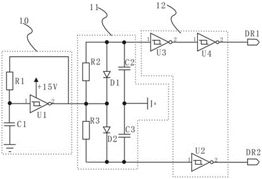
[0032] see figure 1 , the simple pulse switching power supply PWM generation circuit of the present invention includes a resonant module 10, a dead time setting module 11 and a shaping and reversing module 12; the dead time setting module 11 is electrically connected between the resonant module 10 and the reshaping and reversing module 12 , the resonant module 10 self-oscillates to generate a square wave signal, and the square wave signal passes through the dead time setting module 11 and the shaping and inversion module 12 in sequence to obtain the first PWM for corresponding to the MOS tubes of different bridge walls of the driving pulse switching power supply. The pulse signal DR1 and the second PWM pulse signal DR2 have equal duty ratios and a set dead zone.

[0033] In this embodiment, the first resistor R1 ...


PUM


Abstract

The invention discloses a simple pulse switch power supply PWM generation circuit and method. The PWM generation circuit comprises a resonance module, a dead zone time setting module and a shaping reverse module. The dead zone time setting module is electrically connected between the resonance module and the shaping reverse module. The resonance module is subjected to self-excited oscillation to generate square signals. After the square signals pass through the dead zone time setting module and the shaping reverse module in sequence, a first PWM pulse signal and a second PWM pulse signal which are used for driving bridge-wall-different MOS transistors of a pulse switch power supply respectively are obtained, the first PWM pulse signal and the second PWM pulse signal being the same in duty ratio and having set dead zones. The circuit is simple and high in cost performance; the circuit is in complete hardware implementation; the whole processing process does not need the intervention of control circuits such as CPU and the like; the circuit is high in reliability and effectively helps to solve the defects that in the prior arts, the size a chip is big and the number of pins is large; and the peripheral circuit of the circuit only has resonance module and the dead zone time setting module, so that the size of the pulse switch power supply is allowed to be minimized.

Description

technical field [0001] The invention relates to the field of power electronics, in particular to a PWM generating circuit and method for a simple pulse switching power supply. Background technique [0002] With the rapid development of power electronics, isolated pulse switching power supplies are often used as driving power sources on the PWM shaping side and inverter output side of power electronic devices, and the technical requirements have gradually become more stringent. At present, most PWM generators for isolated pulse switching power supplies use integrated control chips, such as SG3525, TL494, etc. These chips have good stability and are easy to purchase in the market; they carry multiple feedback loop control and fault protection functions, and are suitable for pulse switching power supplies. The design often adopts an open-loop approach. This type of chip has a large volume and many pins, and the peripheral circuit is complicated, which is not conducive to the d...

Claims


Application Information

Patent Timeline
Patent Type & Authority Patents(China)
IPC IPC(8): H02M3/155H02M1/38
Inventor 黎香曾
Owner SUZHOU WEICHUANG ELECTRICAL EQUIP TECH
Learn More