Current regulator for modulating brightness levels of solid state lighting

a current regulator and brightness level technology, applied in the direction of electric variable regulation, process and machine control, instruments, etc., can solve the problems of low efficiency, limited to deliver relatively low power, and over-complexity of various led drivers, and achieve the effect of low cost components

Active Publication Date: 2011-03-08
CHEMTRON RES
View PDF8 Cites 122 Cited by
  • Summary
  • Abstract
  • Description
  • Claims
  • Application Information

AI Technical Summary

Benefits of technology

[0017]The exemplary embodiments of the present invention provide numerous advantages. The exemplary embodiments allow for solid state lighting, such as LEDs, to be utilized with the currently existing lighting infrastructure and to be controlled by any of a variety of switches, such as phase modulating dimmer switches, which would otherwise cause significant operation problems for conventional switching power supplies or current regulators. The exemplary embodiments further allow for sophisticated control of the output brightness or intensity of such solid state lighting, and may be implemented using fewer and comparatively lower cost components. In addition, the exemplary embodiments may be utilized for stand-alone solid state lighting systems, or may be utilized in parallel with other types of existing lighting systems, such as incandescent lamps.

Problems solved by technology

For example, a capacitive drop off-line LED driver from On Semiconductor (Application Note AND8146 / D) is a non-isolated driver with low efficiency, is limited to deliver relatively low power, and at most can deliver a constant current to the LED with no temperature compensation, no dimming arrangements, and no voltage or current protection for the LED.
In general, these various LED drivers are overly complicated, such as using secondary side signals (feedback loops) which have to be coupled with the controller primary side, across the isolation provided by one or more transformers.
Such current mode regulators require relatively many functional circuits while nonetheless continuing to exhibit stability problems when used in the continuous current mode with a duty cycle (or duty ratio) over fifty percent.
While these prior art solutions addressed problems of instability, these hysteretic pulse train converters exhibit other difficulties, such as electromagnetic interference, inability to meet other electromagnetic compatibility requirements, and are comparatively inefficient.
Many of these power supplies (i.e., drivers) are effectively incompatible with the existing lighting system infrastructure, such as the lighting systems typically utilized for incandescent or fluorescent lighting.
These power supplies, generally implemented as a form of switching power supplies, are particularly incompatible with phase-modulating “dimmer” switches utilized to alter the brightness or intensity of light output from incandescent bulbs.
Accordingly, replacement of incandescent lamps by LEDs is facing a challenge: either do a complete rewiring of the lighting infrastructure, which is expensive and unlikely to occur, or develop new LED drivers compatible with phase modulation of the input AC voltage by commercially available and already installed dimmers switches.
This proposal is complicated, requires excessively many components to implement, and is not particularly oriented to AC utility lighting.
When coupled with a dimmer, however, its LED regulation is poor and it does not completely support stable operation of the dimmer in the full range of output loads, specifically when both incandescent and LED lamps are being used in parallel.
Typical prior art, off-line AC / DC converters that drive LEDs using phase modulation from a dimmer switch have several problems associated with providing a quality drive to LEDs, such as: (1) such phase modulation from a dimmer switch can produce a low frequency (about 120 Hz) in the optical output, which can be detected by a human eye or otherwise create a reaction in people to the oscillating light; (2) filtering the input voltage may require quite a substantial value of the input capacitor, compromising both the size of the converter and its life; (3) when the triac 80 is turned on, a large inrush current may be created, due to a low impedance of the input filter, which may damage elements of both the dimmer switch 75 and any LED driver; and (4) power management controllers are typically not designed to operate in an environment having phase modulation of input voltage and could malfunction.
As a consequence, the small charging current may not be enough to charge C1 to the diac 85 breakover voltage during one half cycle.
When a dimmer switch is used with a load drawing or sinking a small amount of current, ILOAD80 will provide inconsistent behavior unsuitable for applications with LED drivers.

Method used


Image

  • Current regulator for modulating brightness levels of solid state lighting
  • Current regulator for modulating brightness levels of solid state lighting
  • Current regulator for modulating brightness levels of solid state lighting

Examples


Embodiment Construction

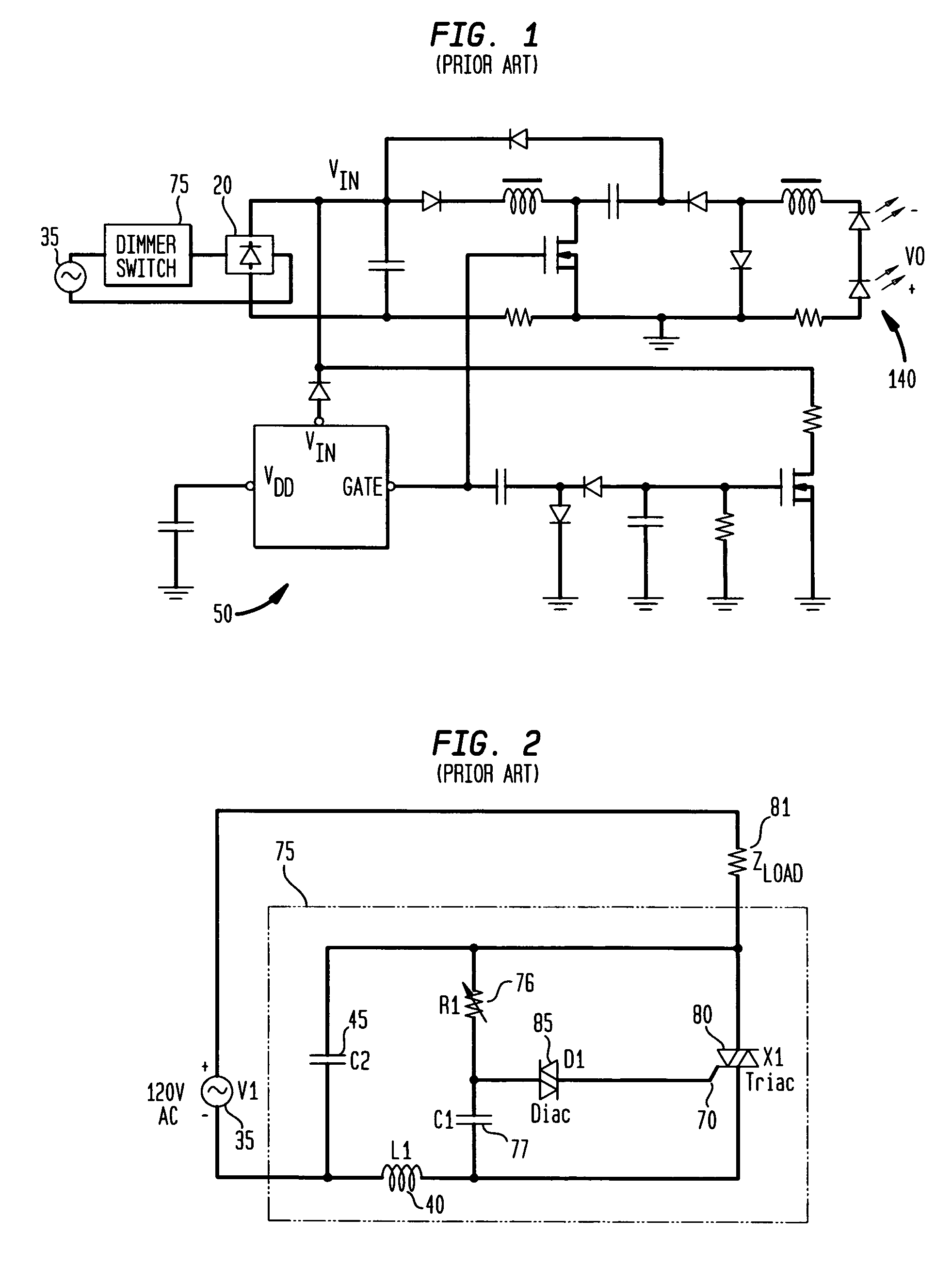
ulated output voltage from a standard dimmer switch.

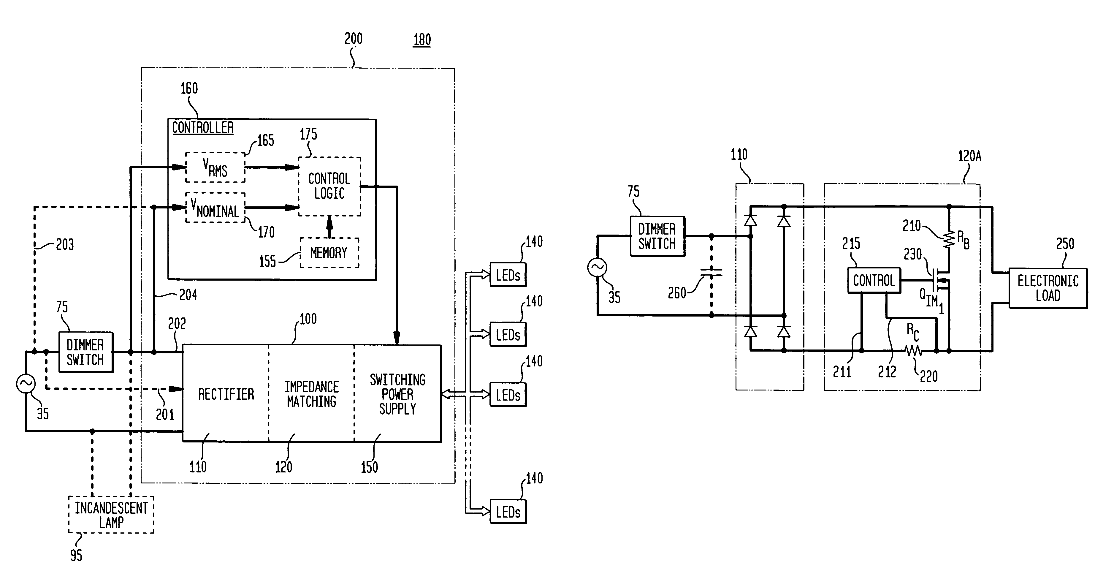
[0035]FIG. 5 is a high-level block and circuit diagram of a generalized prior art current regulator (or converter).

[0036]FIG. 6 is a block diagram of an exemplary first embodiment of a current regulator (or converter) in accordance with the teachings of the present invention.

[0037]FIG. 7 is a block diagram of an exemplary second embodiment of a current regulator (or converter) in accordance with the teachings of the present invention.

[0038]FIG. 8 is a circuit diagram of an exemplary first embodiment of an impedance matching circuit for a current regulator (or converter) in accordance with the teachings of the present invention.

[0039]FIG. 9 is a circuit diagram of an exemplary second embodiment of an impedance matching circuit for a current regulator (or converter) in accordance with the teachings of the present invention.

[0040]FIG. 10 is a circuit diagram of an exemplary embodiment of a switching power supply for a current regulato...


PUM


Abstract

An exemplary embodiment provides a current regulator for controlling variable brightness levels for solid state lighting. The current regulator is couplable to a phase-modulating switch, such as a dimmer switch, which is coupled to an AC line voltage. An exemplary current regulator includes a rectifier; a switching power supply providing a first current; an impedance matching circuit; and a controller. The impedance matching circuit is adapted to provide a second current through the phase-modulating switch when a magnitude of the first current is below a first predetermined threshold, such as a holding current of a triac of the phase-modulating switch. The controller is adapted to determine a root-mean-square (RMS) voltage level provided by the phase-modulating switch from the AC line voltage and to determine a duty cycle for pulse-width current modulation by the switching power supply in response to the comparison of the RMS voltage level to a nominal voltage level.

Description

CROSS-REFERENCE TO A RELATED APPLICATION[0001]This application claims priority to and is a conversion of U.S. Provisional Patent Application Ser. No. 60 / 760,157, filed Jan. 20, 2006, inventors Anatoly Shteynberg et al., entitled “Off-Line LED Driver with Phase Modulation”, which is commonly assigned herewith, the contents of which are incorporated herein by reference, and with priority claimed for all commonly disclosed subject matter.FIELD OF THE INVENTION[0002]The present invention in general is related to power conversion, and more specifically, to a system, apparatus and method for supplying power to solid state lighting devices, such as for providing power to light emitting diodes (“LEDs”) and LEDs integrated with digital controllers or processors.BACKGROUND OF THE INVENTION[0003]A wide variety of off-line LED drivers are known. For example, a capacitive drop off-line LED driver from On Semiconductor (Application Note AND8146 / D) is a non-isolated driver with low efficiency, is ...

Claims


Application Information

Patent Timeline
Patent Type & Authority Patents(United States)
IPC IPC(8): G05F1/00
CPCH05B33/0815H05B33/0851Y02B20/347H05B45/3575H05B45/345Y02B20/30H05B45/3725H05B45/3577H05B45/10H05B45/375
Inventor SHTEYNBERG, ANATOLYRODRIGUEZ, HARRY
Owner CHEMTRON RES
Why Eureka
Try Eureka