
Antenna device, and a portable telecommunication apparatus including such an antenna device

a portable telecommunications and antenna technology, applied in the field of radio communication, can solve the problems of poor talking position performance, reduced available printed circuit board area, etc., and achieve the effect of avoiding interference between the two antennas, low development cost and excellent performan

Inactive Publication Date: 2006-11-07
TELEFON AB LM ERICSSON (PUBL)
View PDF13 Cites 30 Cited by
  • Summary
  • Abstract
  • Description
  • Claims
  • Application Information

AI Technical Summary

Benefits of technology

[0008]The present invention seeks to remedy the problems set out above. In particular, it is an object of the invention to provide an antenna device for a miniaturized mobile telephone, which allows excellent performance both for a multi-band cellular antenna and a short-range supplementary communication antenna (e.g. Bluetooth®). Additionally, the desired solution is one where interference between the two antennas is avoided without a major coat penalty, and which allows low costs for development and production of antenna components.
[0011]By placing the Bluetooth® antenna in the top area of the back cover of the mobile telephone, the antenna performance gets better. Low component and development costs are available thanks to the invention. The proposed antenna device has a small size and can be encapsulated in a thin flexible rubber or plastic housing, allowing high flexibility for the designer of the mobile telephone.

Problems solved by technology

However, as mobile telephones get smaller and smaller in size, the available printed circuit board area also decreases.
Cellular radio circuitry must be prioritized in the layout of the printed circuit board, and as a result, in existing telephones, the Bluetooth® antenna has been placed in areas on the keyboard side of the printed circuit board, where the performance in talking position is not good.

Method used


Image

  • Antenna device, and a portable telecommunication apparatus including such an antenna device
  • Antenna device, and a portable telecommunication apparatus including such an antenna device
  • Antenna device, and a portable telecommunication apparatus including such an antenna device

Examples


Embodiment Construction

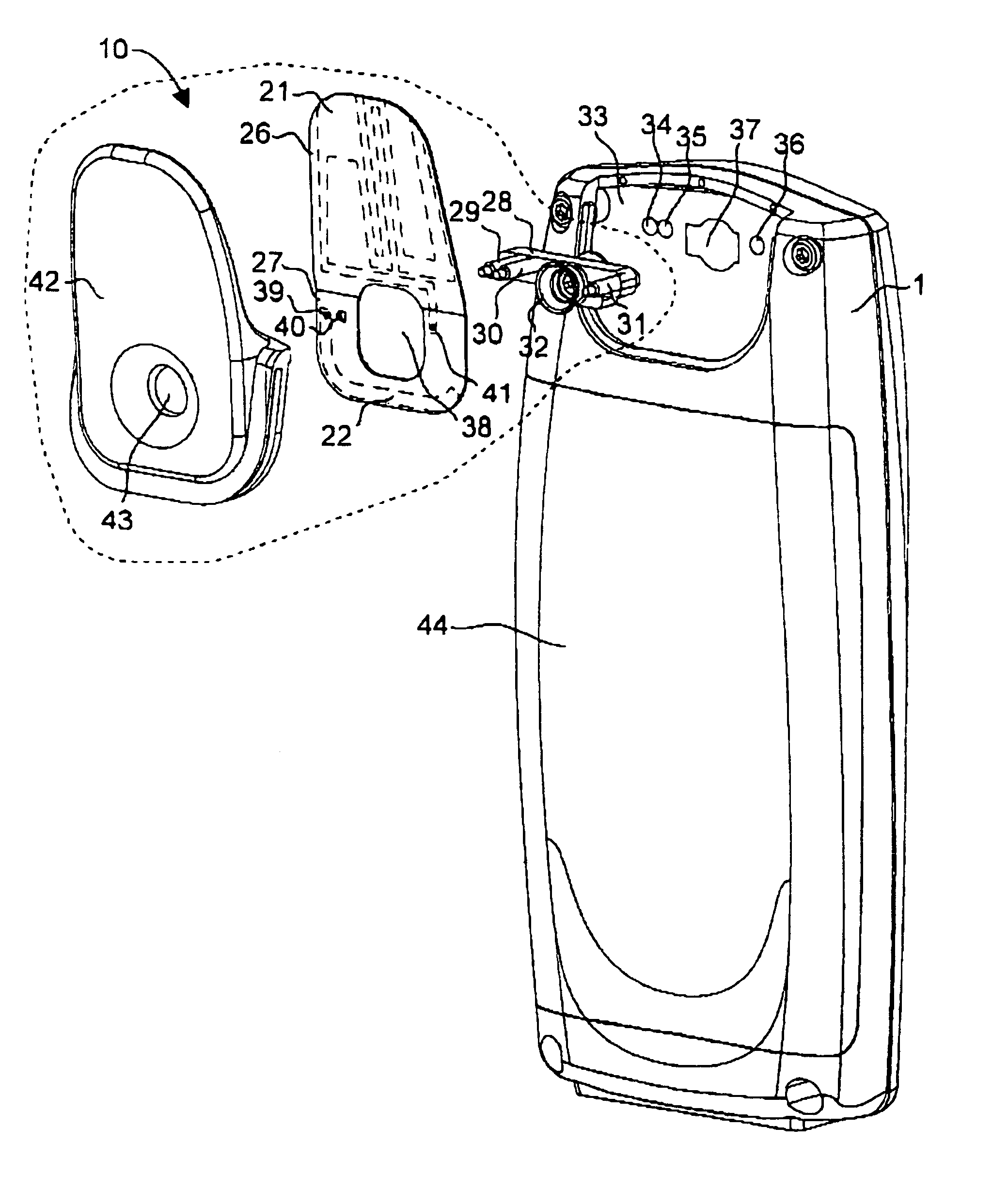
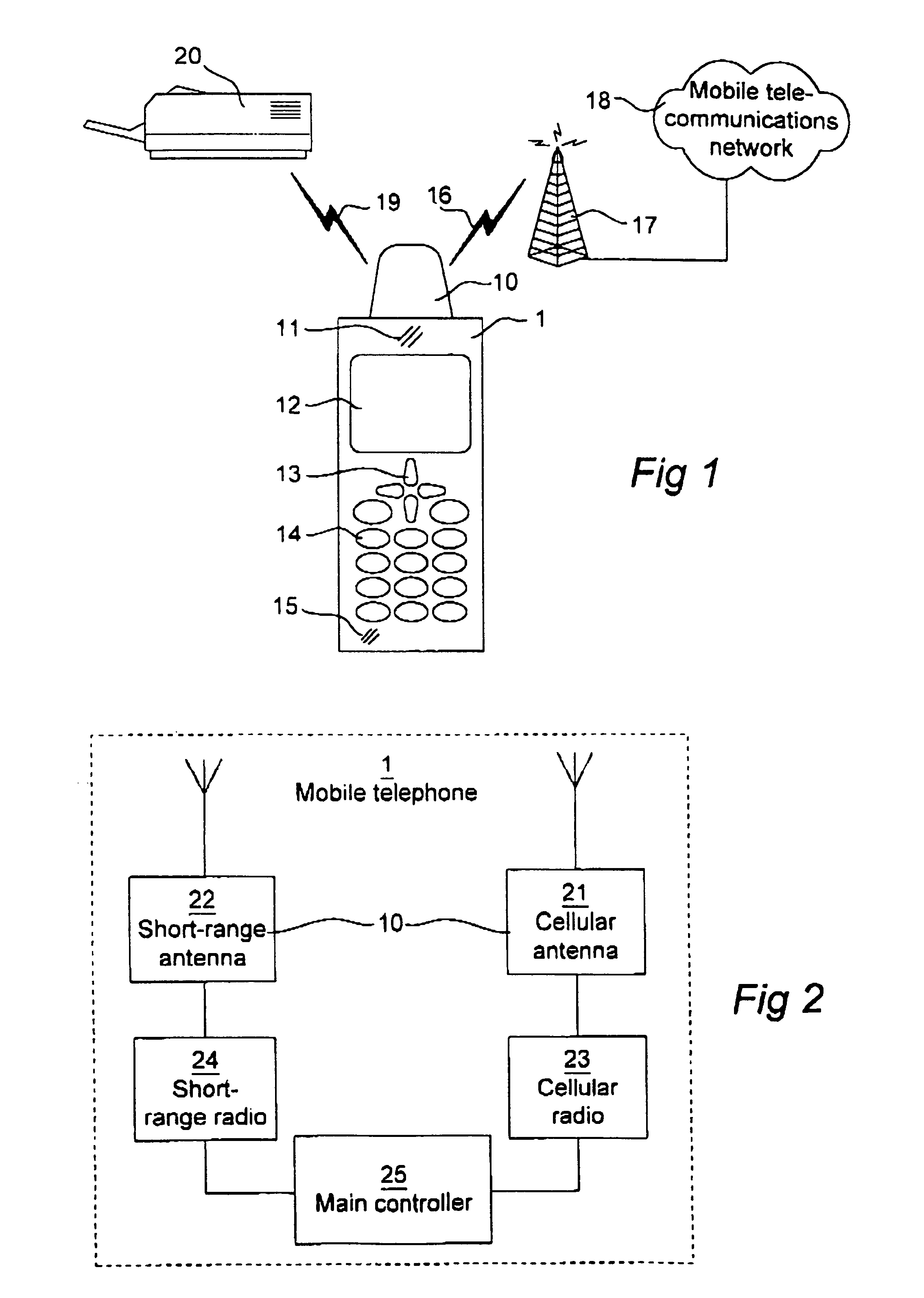
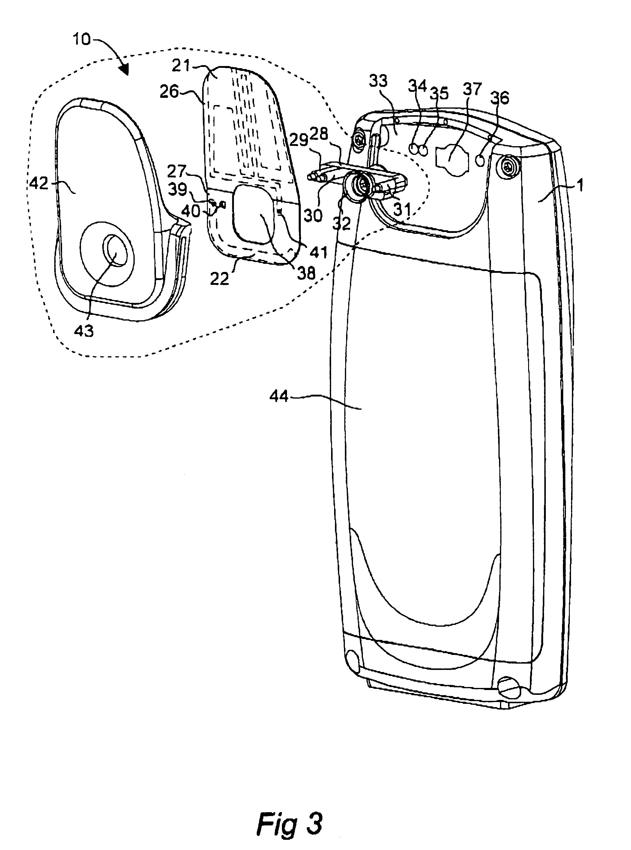
[0022]FIGS. 1–3 illustrate a mobile telephone 1 as a schematic front view, a block diagram and a detailed perspective rear view, respectively. As seen in the drawings, the mobile telephone 1 has an antenna device 10, which is mounted to an upper rear portion of the mobile telephone 1, immediately above a battery 44. The antenna device 10 has a cellular antenna 21, which is electrically connected to a cellular radio transceiver 23 on a printed circuit board 33 (FIG. 3) through an antenna connector 28, as will be described in more detail later.

[0023]Thus, the mobile telephone 1 may establish a wireless link 16 to a radio station (base station) 17 in a mobile telecommunications network 18, such as GSM, UMTS or D-AMPS.

[0024]The antenna device 10 moreover comprises a short-range supplementary communication antenna 22, which is referred to as the “Bluetooth® antenna” in the rest of this section. The Bluetooth® antenna 22 is electrically connected to Bluetooth® radio circuitry on the print...


PUM


Abstract

An antenna device (10) for a portable telecommunication apparatus (1) has a first antenna (21) adapted for telecommunication in at least a first frequency band and a second antenna (22) adapted for short-range supplementary communication in a second frequency band. The first and second antennas (21, 22) are formed on a common support element (26, 27).

Description

TECHNICAL FIELD[0001]The present invention relates co the field of radio communication and, in more particular, to an antenna device for use in a portable telecommunication apparatus of the type having a first antenna adapted for telecommunication in at least a first frequency band and a second antenna adapted for short-range supplementary communication in a second frequency band.PRIOR ART[0002]Examples of a portable communication apparatus as set out above are a mobile telephone, a cordless telephone, a portable digital assistant, a communicator, a paging device, an electronic payment device, or a portable navigating device. Among these, the mobile or cellular telephone is currently believed to be the most prominent in terms of market penetration and sales volumes. Therefore, for the rest of this document, reference will be made to a mobile or cellular telephone for any commercially available mobile communications network, such as GSM, UMTS or D-AMPS. However, the invention is not ...

Claims


Application Information

Patent Timeline
IPC IPC(8): H01Q1/24H01Q1/38H01Q1/42H01Q5/00H01Q9/42H01Q21/30H04M1/02H04W88/02
CPCH01Q1/243H01Q21/30H01Q5/40H04M2250/02H04M1/0202
Inventor OLSSON, MATSYING, ZHINONG
Owner TELEFON AB LM ERICSSON (PUBL)
Learn More