Method and system for economical beam forming in a radio communication system

a radio communication system and beam forming technology, applied in the direction of multiplex communication, wireless communication, orthogonal multiplex, etc., can solve the problems of increasing the number of rf transceiver systems required in the base terminal station (bts), adding complexity and cost to the system, and expensive, and the weight and size of rf cabling tends to be significan

Inactive Publication Date: 2006-05-18
PROCTOR JAMES A JR +4
View PDF22 Cites 32 Cited by
  • Summary
  • Abstract
  • Description
  • Claims
  • Application Information

AI Technical Summary

Benefits of technology

[0016] Addressing the problems of the prior art beam forming systems, the principles of the present invention apply digital multiplexing techniques to a beam forming system to reduce RF components and improve system performance. The reduction in RF components eliminates the need for RF channel-to-RF channel calibration and reduces weight, complexity, and cost. Reducing weight, complexity, and cost allows the number of elements in the antenna array to be increased. More antenna elements results in at least the following benefits: higher user capacity, higher SNR, more antenna beams, narrower antenna beams, higher in-building penetration, and lower cost components.
[0019] The system may further extract the given signal from the given element. Extracting the given signal includes multiplying the composite baseband signal by the code applied to the given signal. The system then applies a weight to the extracted signal. Further, the system may (i) extract a subset of signals from the baseband signals, (ii) apply weights to the extracted signals, and (iii) sum the multiple weighted extracted signals to yield signals producing a spatial beam forming effect. This provides beam forming in a simple way.
[0020] To produce beam forming in an elegant way, the system (a) replicates the codes applied to the signals at the elements, (b) applies weights to the replicated codes, (c) sums the coded weights to form a composite signal, (d) multiplies the received baseband composite signal by the weighted composite signal, (e) forms a single composite signal, and (f) integrates the single composite signal over the duration of the code to yield a spatial beam forming effect.

Problems solved by technology

The problem with traditional beam forming systems is that the number of RF transceiver systems required in a base terminal station (BTS) adds complexity and cost to the system.
Since the RF transceiver, cabling, and other associated components tend to have gain and phase offset drift over time, temperature, and humidity, the traditional beam forming system must be supported by plural, expensive, calibration electronics to maintain performance.
Moreover, in traditional beam forming systems, the weight and size of RF cabling tends to be significant for single-pole structures that support the antenna arrays.
Fewer antenna elements in an antenna array result in fewer users that can be supported by a beam forming system at any one time.

Method used


Image

  • Method and system for economical beam forming in a radio communication system
  • Method and system for economical beam forming in a radio communication system
  • Method and system for economical beam forming in a radio communication system

Examples


Embodiment Construction

[0048] A description of preferred embodiments of the invention follows.

[0049]FIG. 3A is a block diagram of a base transceiver station 300 in which the principles of the present invention are employed. The base transceiver station 300 includes an antenna assembly 302, base electronics 306, and base station tower 313, on which the antenna assembly 302 is supported.

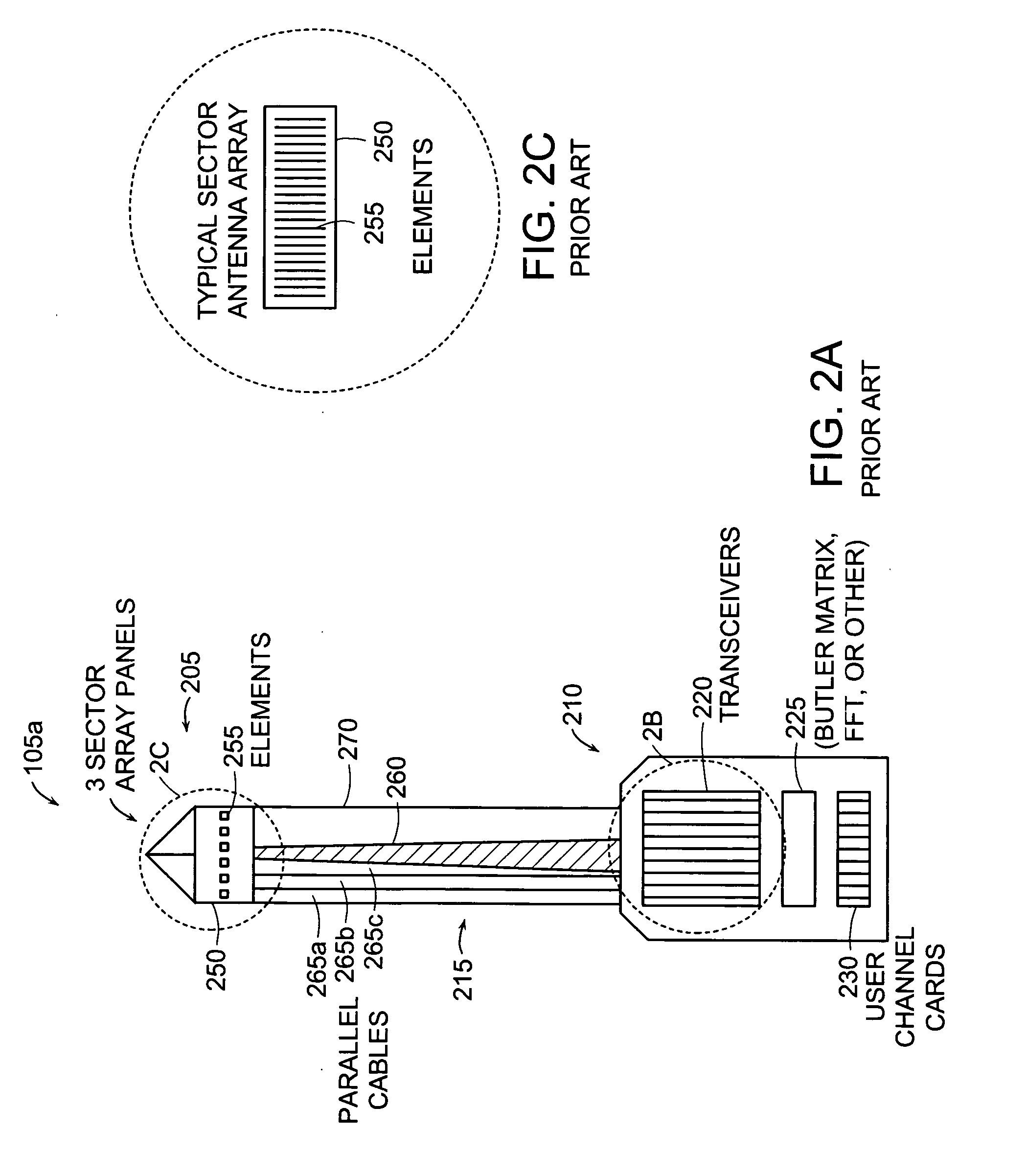
[0050] The antenna assembly 302, in this embodiment, includes three sector antenna arrays 305. The sector antenna arrays 305 include electronics, described later, and elements 255.

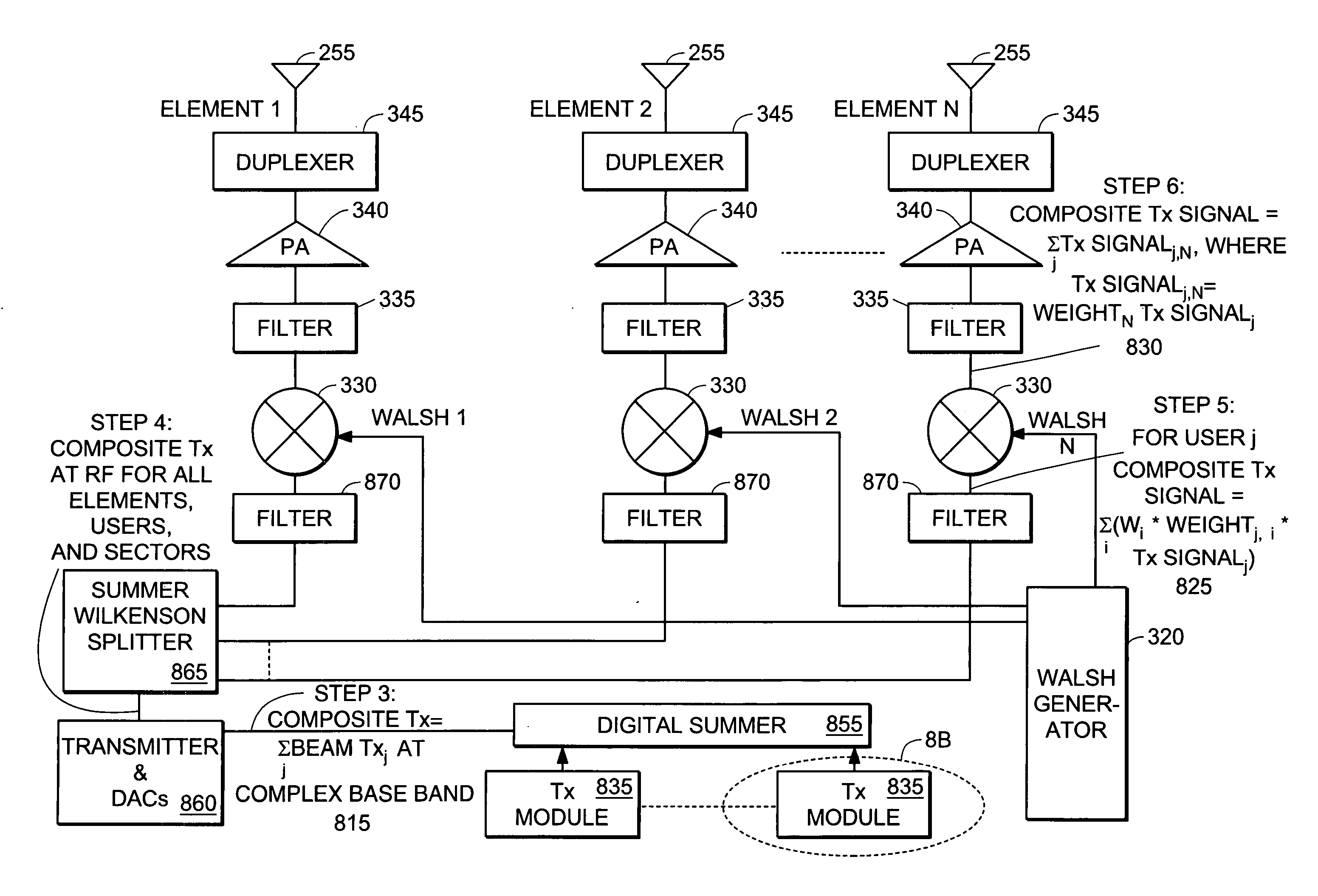
[0051] The base electronics 306 include a single transceiver 370 for all elements 205 of the sector antenna arrays 305. Further, the base electronics 306 include channel cards 365 with integrated weighting electronics, obviating separate weighting electronics 225 (FIG. 2A).

[0052] The base station tower 313 include only a single RF cable 265a in this embodiment. In other embodiments, the RF cable 265a is replaced with a fiber optic cable, wire c...


PUM


Abstract

Individual RF cables span between element / transceiver pairs in traditional beam forming systems, and the number of elements in an array used for beam forming is thus restricted. To reduce the number of RF cables but maintain or increase the number of elements in an antenna array, an embodiment of the present invention includes electronics at the base of an antenna tower that apply digital multiplexing codes to signals communicated to electronics located at the top of the antenna tower. The electronics at the top demultiplex the signals and transmit them via the antenna array. Received RF signals are processed in a like manner in a reverse direction. Fewer transmission paths (e.g., RF or fiber optic cables) than the number of elements in the antenna array can be used. More antenna elements provide benefits, such as higher user capacity, more antenna beams, narrower antenna beams, and higher in-building penetration.

Description

RELATED APPLICATION(S) [0001] This application is a divisional of U.S. application Ser. No. 09 / 791,503, filed on Feb. 23, 2001, which claims the benefit of U.S. Provisional Application No. 60 / 184,754, filed on Feb. 24, 2000, the entire teachings of the above application(s) are incorporated herein by reference.BACKGROUND OF THE INVENTION [0002] In wireless voice and data communications, it is desirable to maximize the number of users in a base transceiver station (BTS) sector while at the same time providing high signal quality (i.e., high SNR) for the users. One way to achieve both conditions is through the use of a beam forming antenna. A BTS can generate plural directed beams by employing an antenna array and digitizing signals transmitted to and received from the antenna array in a weighted manner (i.e., amplitude and / or phase) that produces the plural beams. Since the beams have high gain in the direction of the main lobe of the composite beam, high SNR is achieved. And, since t...

Claims


Application Information

Patent Timeline
Patent Type & Authority Applications(United States)
IPC IPC(8): H04J11/00H04B7/04H04B7/08H04W88/08
CPCH01Q1/246H01Q3/26H04B7/0408H04B7/0678H04B7/0848H04J13/004H04W88/08
Inventor PROCTOR, JAMES A. JR.LAMONT, LAWRENCE WAYNE JR.NELSON, GEORGE RODNEY JR.ROUPHAEL, ANTOINE J.HOFFMANN, JOHN E.
Owner PROCTOR JAMES A JR
Why Eureka
Try Eureka