Switching power supply device

a power supply device and power supply technology, applied in the direction of power conversion systems, dc-dc conversion, climate sustainability, etc., can solve the problems of increasing the size of the substrate, the difficulty of forming it on the semiconductor chip, and the cost of assembly of the elements, so as to reduce the ripple voltage

Active Publication Date: 2010-01-28
TEXAS INSTR INC
View PDF4 Cites 130 Cited by
  • Summary
  • Abstract
  • Description
  • Claims
  • Application Information

AI Technical Summary

Benefits of technology

[0021]With said switching power supply device, at said second capacitor of said integrator, a voltage corresponding to the integration value of the voltage applied to said inductor is generated, and a signal similar to the ripple voltage generated at the second capacitor is generated by said amplitude converter as a ripple signal corresponding to the ripple current flowing through said inductor. The amplitude of said ripple signal is converted by said amplitude converter so that it decreases the ripple voltage of said second capacitor. As a result, even if the time constant of said integrator is small, it is still possible to convert the amplitude of said ripple signal into an appropriate amplitude, so that it is possible to form said integrator with elements with appropriate element values that allow integration on the semiconductor chip.

Problems solved by technology

If the amplitude of ripple voltage Vrp is too large, the deviation between the DC level defined by reference voltage Vref and the DC level of actual output voltage Vout increases, which is undesirable for guaranteeing the DC precision of output voltage Vout.
If the capacitance of the capacitor were, e.g., several thousand pF, it would be difficult to form it on a semiconductor chip, and it would have to be assembled as a discrete element on the substrate.
Usually, in the switching power supply device shown in FIG. 19, resistor R35 and capacitors C34, C35 must be assembled as discrete elements on a substrate, so that the size of the substrate increases, as does the cost of assembly of the elements, which is undesirable.

Method used


Image

  • Switching power supply device
  • Switching power supply device
  • Switching power supply device

Examples


embodiment 1

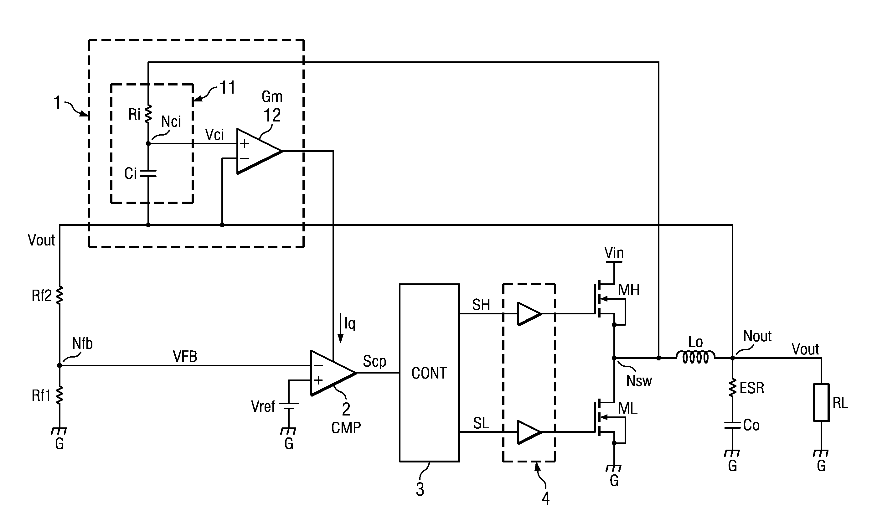
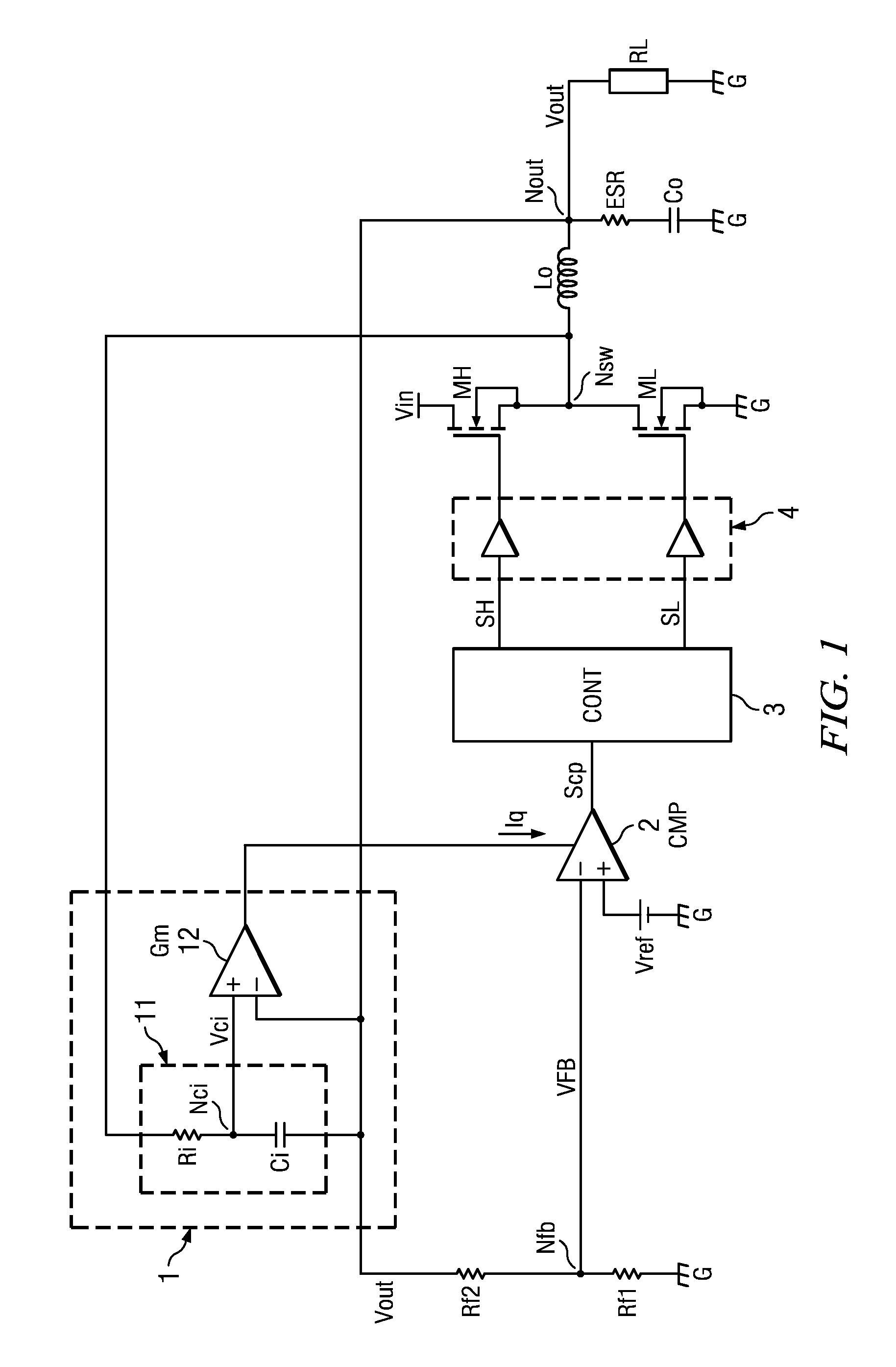
[0056]FIG. 1 is a diagram illustrating a constitutional example of the switching power supply device in Embodiment 1 of the present invention.

[0057]The switching power supply device shown in FIG. 1 comprises the following parts: ripple signal generator 1, comparator 2, controller 3, driver 4, resistors Rf1, Rf2 for voltage feedback, N-type MOS transistors ML and MH, inductor Lo, and capacitor Co. Said ripple signal generator 1 has CR integrator 11 consisting of capacitor Ci and resistor Ri, and voltage / current converter 12.

[0058]Capacitor Co is an embodiment of the first capacitor in the present invention. Inductor Lo is an embodiment of the inductor in the present invention. MOS transistors ML and MH represent an embodiment of the switching circuit in the present invention. Said ripple signal generator 1 is an embodiment of the ripple signal generator of the present invention. Said comparator 2 is an embodiment of the comparator of the present invention. CR integrator 11 is an embo...

embodiment 2

[0111]Embodiment 2 of the present invention will be explained below.

[0112]FIG. 6 is a diagram illustrating a constitutional example of the switching power supply device in Embodiment 2 of the present invention.

[0113]For the switching power supply device shown in FIG. 6, ripple signal generator 1 in the switching power supply device shown in FIG. 1 is replaced by ripple signal generator 1A, and the other structural elements are the same as those of the switching power supply device shown in FIG. 1. For ripple signal generator 1A, in addition to the same constitution as that shown in FIG. 1 (CR integrator 11, voltage / current converter 12), there is also voltage division circuit 13 that divides the voltage generated on capacitor Ci. Said voltage division circuit 13 is an embodiment of the voltage division circuit of the present invention. Said voltage division circuit 13 contains resistors R5 and R6 connected in series. One terminal of resistor R6 is connected to node Nci, and the othe...

embodiment 3

[0115]In the following, an explanation will be given regarding Embodiment 3 of the present invention.

[0116]FIG. 7 is a diagram illustrating a constitutional example of the switching power supply device in Embodiment 3 of the present invention.

[0117]For the switching power supply device shown in FIG. 7, ripple signal generator 1 in the switching power supply device shown in FIG. 1 is replaced by ripple signal generator 1B, to be explained below, while the other structural elements are the same as those of the switching power supply device shown in FIG. 1.

[0118]Said ripple signal generator 1B has CR integrator 11B, voltage / current converter 12, and voltage divider circuits 13B and 14. Said voltage divider circuit 13B is an embodiment of the first voltage divider circuit of the present invention. Said voltage divider circuit 14 is an embodiment of the first voltage divider circuit of the present invention. Said CR integrator 11B contains resistor Ri and capacitor Ci connected in series...


PUM


Abstract

A switching power supply device for a ripple control system that can obtain the ripple component with the necessary amplitude without using discrete elements. On capacitor Ci of CR integrator 11, a voltage is generated corresponding to the integration value of the voltage applied to inductor Lo. The ripple voltage generated on capacitor Ci has a waveform similar to that of the ripple current flowing through inductor Lo. The voltage of capacitor Ci is converted into current Iq by voltage / current converter 12, and the current is injected in resistor R3 arranged on the transmission path of output feedback voltage VFB in comparator 2. Resistor R3 generates ripple voltage (Iqxr3) corresponding to the ripple current flowing through inductor Lo. The synthetic voltage of the ripple voltage and output feedback voltage VFB is compared to reference voltage Vref.

Description

FIELD OF THE INVENTION[0001]The present invention pertains to a switching power supply device with high efficiency and high-speed response. For example, the present invention pertains to a switching power supply device of the ripple control system that controls the output on the basis of comparing the ripple component of the output to a threshold value.[0002]With rapid popularization of cell phones and other mobile devices, there is an increasing demand for improved performance of switching power supply devices for mobile equipment. Great efforts have been made to develop such techniques as low-voltage operation, high efficiency and quick response, and fewer parts in the switching power supply device.[0003]FIG. 17 is a diagram illustrating a constitutional example of the switching power supply device of the voltage mode system in the prior art. In the example shown in FIG. 17, a voltage buck-type converter is composed of MOS transistors MH, ML, inductor Lo and capacitor Co. Here, th...

Claims


Application Information

Patent Timeline
Patent Type & Authority Applications(United States)
IPC IPC(8): G05F1/10
CPCH02M1/15Y02B70/1466H02M3/1588Y02B70/10
Inventor KATSUYA, GOTOMIYAZAKI, TAKAHIRO
Owner TEXAS INSTR INC
Why Eureka
Try Eureka