Step-up dc-dc converter

a dc-dc converter and step-up technology, applied in the field of step-up dc-dc converters, can solve the problems of inability to simply reduce the imax irrespective, inability to simply reduce the imax, so as to prevent humming or malfunction, reduce the ripple voltage of outpu

Inactive Publication Date: 2012-12-06
MITSUMI ELECTRIC CO LTD
View PDF7 Cites 9 Cited by
  • Summary
  • Abstract
  • Description
  • Claims
  • Application Information

AI Technical Summary

Benefits of technology

[0014]The present invention was conceived in consideration of the situation described in the above, and an object of which is to provide a step-up DC-DC converter based on the PFM control system, capable of reducing the ripple voltage of output while achieving a desired level of maximum output current value Iout(MAX), while successfully preventing the humming or malfunction, without modifying external components (L1, C0).

Problems solved by technology

Increase in ΔVp−p has unfortunately resulted in humming of the inductor or the output capacitor, and malfunction of devices.
It is, therefore, not possible to simply reduce Imax irrespective of Iout(MAX).
It is, however, not always possible to modify the values of the output capacitor C0 or the inductor L1, because of characteristics required for the DC-DC converter.

Method used


Image

  • Step-up dc-dc converter
  • Step-up dc-dc converter
  • Step-up dc-dc converter

Examples


Embodiment Construction

[0022]Preferred embodiments of the present invention will be explained below, referring to the attached drawings.

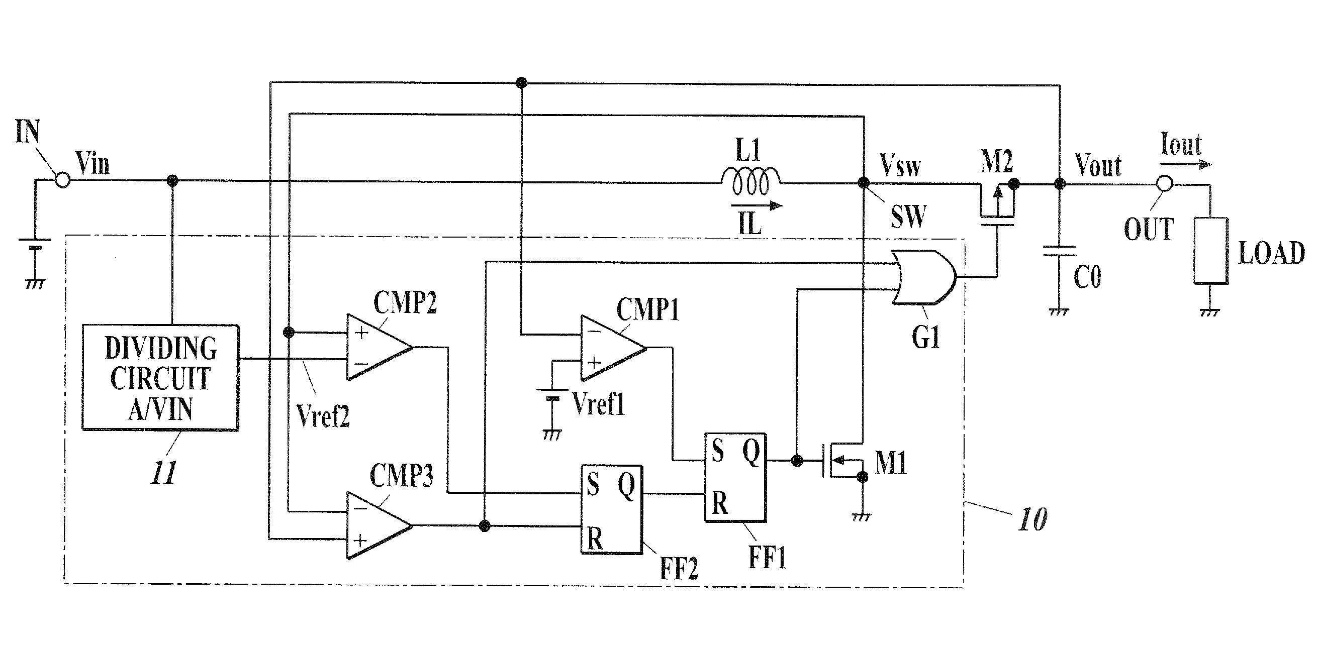
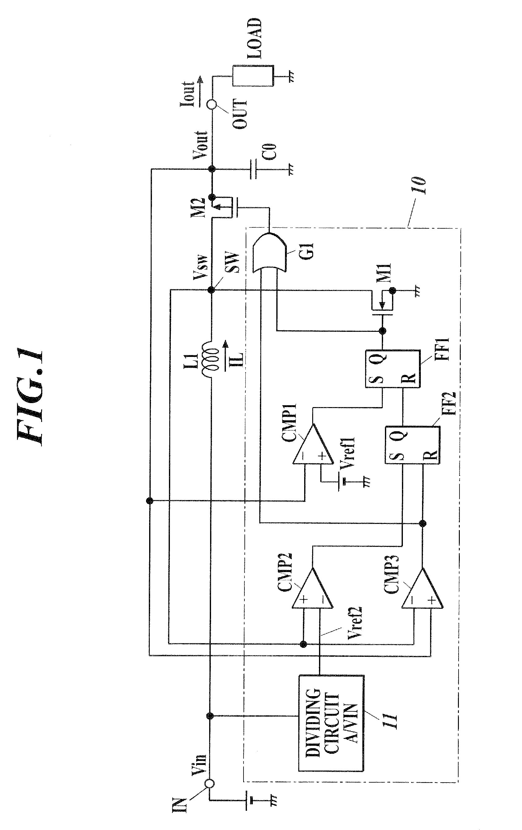
[0023]FIG. 1 is a drawing illustrating one embodiment of the step-up DC-DC converter, based on the PFM (pulse frequency modulation) system for output control, of the present invention.

[0024]The DC-DC converter of this embodiment has a coil L1, a drive switching element M1, a rectifying switching element M2, a switching control circuit 10, and an output smoothing capacitor C0. The coil L1 is an inductor having one terminal thereof connected to an voltage input terminal IN through which DC input voltage Vin is applied. The drive switching element M1 is connected between the other terminal of the coil L1 and a grounding point. An N-channel MOSFET (insulated-gate field effect transistor) may be used as the drive switching element M1. The rectifying switching element M2 is connected between a connection node (terminal SW) of the coil L1 and the switching element M1, and an out...


PUM


Abstract

A step-up DC-DC converter has a switching element for feeding current to an inductor; a rectifier connected to the output side of the inductor; and a control circuit performing on / off control of the switching element, based on an output voltage and a voltage corresponded to the inductor current. The control circuit further has a first voltage comparator circuit detecting fall of the output voltage down to the first reference voltage; a second voltage comparator circuit detecting that the inductor current reached a predetermined current value; and a voltage generation circuit generating a voltage inversely proportional to an input voltage and feeds the voltage, as a second reference voltage, to the second voltage comparator circuit. The switching element turns on, when the output voltage fell down to the first reference voltage, whereas the switching element turns off, when voltage proportional to the inductor current rose up to the second reference voltage.

Description

CROSS-REFERENCE TO RELATED APPLICATION[0001]The present U.S. patent application claims a priority under the Paris Convention of Japanese patent application No. 2011-125906 filed on Jun. 6, 2011 which shall be a basis of correction of an incorrect translation, and is incorporated by reference herein.BACKGROUND OF THE INVENTION[0002]1. Field of the Invention[0003]The present invention relates to a step-up power supply used for DC voltage conversion, based on the switching regulator system, and in particular to a step-up DC-DC converter which controls output based on the PFM (pulse frequency modulation) system.[0004]2. Description of Related Art[0005]DC-DC converters based on the switching regulator system have been known as a sort of circuit capable of converting DC input voltage and outputting a converted DC voltage having a different potential. The DC-DC converters are classified into those of step-up type and step-down type. The DC-DC converter has a drive switching element; a rect...

Claims


Application Information

Patent Timeline
Patent Type & Authority Applications(United States)
IPC IPC(8): G05F1/10
CPCH02M3/156H02M2001/0022H02M1/0022
Inventor TABUCHI, HITOSHIHIROSHIMA, TAKASHI
Owner MITSUMI ELECTRIC CO LTD
Why Eureka
Try Eureka