Power converter circuitry and method
a technology of power converters and circuits, applied in the direction of pulse conversion, constant-current supply dc circuits, instruments, etc., can solve the problems of catastrophic circuit failure and huge efficiency loss
- Summary
- Abstract
- Description
- Claims
- Application Information
AI Technical Summary
Benefits of technology
Problems solved by technology
Method used
Image
Examples
first embodiment
Section 1.1.1 First Embodiment of PWM Timing Generator
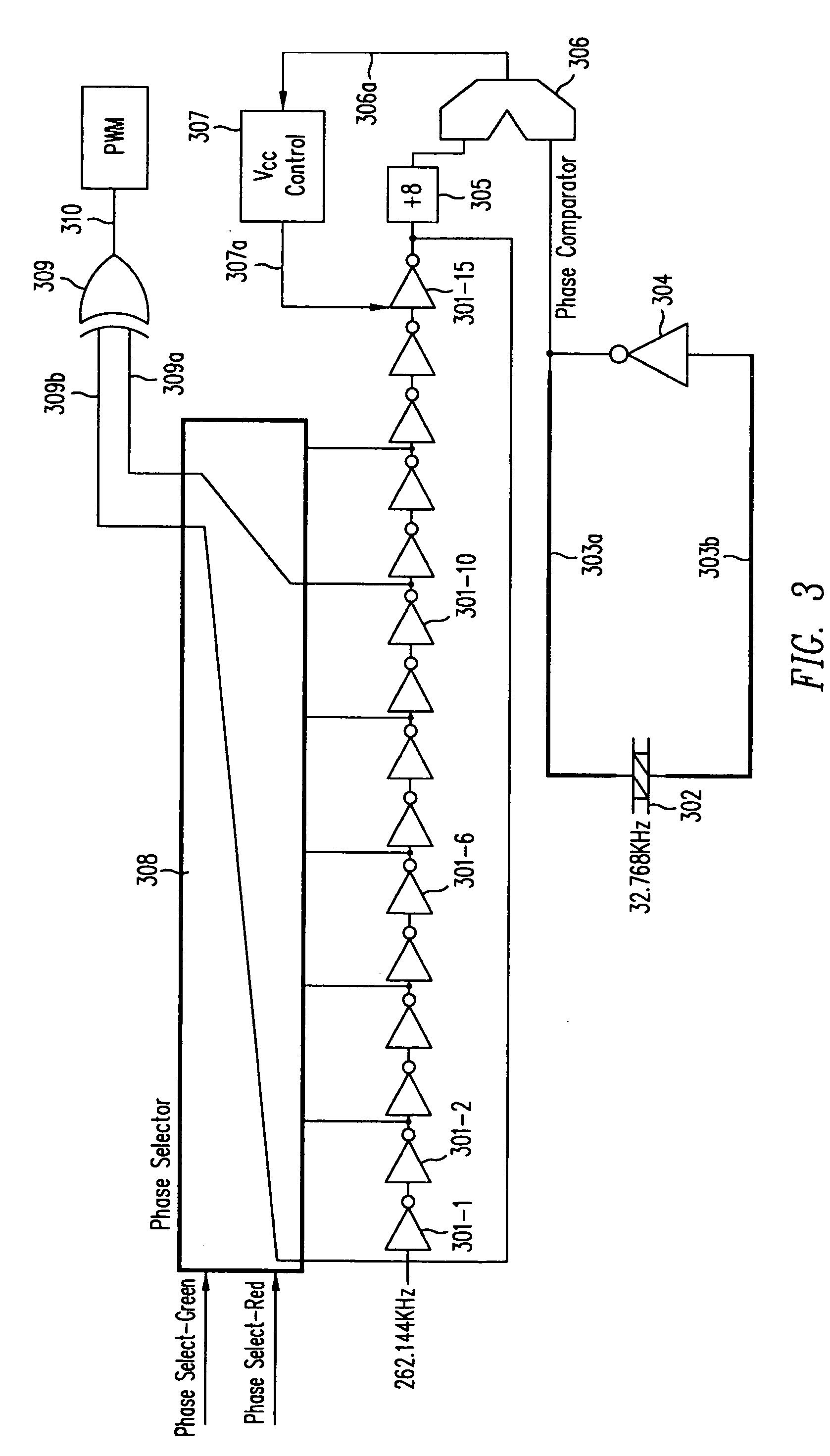
[0178] FIG. 3 shows a supply management controller of a type in accordance with this invention. As shown in FIG. 3, a ring oscillator includes inverters 301-1 through 301-15 connected in series. In an actual embodiment of this invention, the ring oscillator may include a larger number of series-connected inverters. For example, a thousand inverters can be connected in series, with the result that the duty cycle achieved by the controller of this invention can be almost 100%. However, to simplify explanation, only 15 inverters will be illustrated in this detailed description. The inverters each have inherently a delay ".DELTA.," which is the elapsed time between the time a signal is applied to the input lead to the inverter and the time the resulting output signal is obtained on the output lead of each inverter. This time ".DELTA." is a function of the voltage applied to the components contained within the inverter. By varying the...
second embodiment
Section 1.1.2 Second Embodiment of the PWM Timing Generator
[0185] FIG. 4 shows an alternative embodiment of the invention employing counters and comparators to generate a pulse width modulated signal. A five bit counter 41 (although a different number of bits can be used if desired) counts from 0 to 31 driven by a 16.7772 MHz signal. The instantaneous count from 5 bit counter 41 is sent on 5-bit bus 42 to comparators 43a and 43b, each of which compares the count to a reference count stored in it. Digital comparator 43a will store one count determined by the signals on phase select bus 44a and digital comparator 43b will store a second count determined by the signals on phase select bus 44b. The signals on phase select bus 44a and phase select bus 44b are determined by external circuitry which measures the voltage on the load capacitor and the current into the load capacitor and compares the voltage and current to reference values to determine the extent to which the charge on the lo...
PUM
 Abstract
Description
Claims
Application Information
 - R&D
- Intellectual Property
- Life Sciences
- Materials
- Tech Scout
- Unparalleled Data Quality
- Higher Quality Content
- 60% Fewer Hallucinations
Browse by: Latest US Patents, China's latest patents, Technical Efficacy Thesaurus, Application Domain, Technology Topic, Popular Technical Reports.
© 2025 PatSnap. All rights reserved.Legal|Privacy policy|Modern Slavery Act Transparency Statement|Sitemap|About US| Contact US: help@patsnap.com


