
Condensive load protection device of self-excited generator

A technology of capacitive load and protection device, which is applied to control generators, control generators and electrical components through magnetic field changes, and can solve problems such as inability to use, inability to obtain grid voltage, and large heat generation, and to prevent AVR damage. Effect

Active Publication Date: 2013-03-27
HONDA MOTOR CO LTD
View PDF1 Cites 1 Cited by
  • Summary
  • Abstract
  • Description
  • Claims
  • Application Information

AI Technical Summary

Problems solved by technology

[0011] Although devices such as transistors and FETs are used to form a short-circuit circuit for capacitive load protection, there is a problem that in the above-mentioned self-bias circuit 40, the counter electromotive voltage generated in the rotor 5 cannot be obtained for the transistor 42, 43 is sufficient gate voltage, therefore, these devices cannot be used in the saturated action region, and large devices with high heat generation are required

Method used


Image

  • Condensive load protection device of self-excited generator
  • Condensive load protection device of self-excited generator
  • Condensive load protection device of self-excited generator

Examples


Embodiment Construction

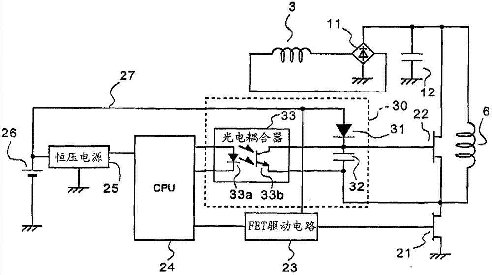
[0061] A capacitive load protection device for a self-excited generator according to an embodiment of the present invention will be described below with reference to the accompanying drawings. figure 1 It is a block diagram showing the configuration of main parts of the self-excited generator capacitive load protection device of the present invention. exist figure 1 In, about with Figure 4 The same structure is labeled with the same reference number.

[0062] Such as Figure 4 As shown, a self-excited generator 1 connected with a capacitive load protection device is driven by an engine, and is equipped with an automatic voltage regulator 10. The automatic voltage regulator 10 supplies current to the field winding 6 according to the fluctuation of the output voltage of the generator. The current It is obtained by rectifying the output of the field coil 3 wound on the generator by the rectifier 11 . The capacitor 12 is a capacitor for smoothing the output voltage of the rec...


PUM


Abstract

In a self-excited generator 1 including an automatic voltage regulator (AVR) 10, a condensive load protection device includes: a field current control driver 21 which is connected to the field winding 6 in series and controlled to be ON / OFF by a drive circuit 23 of the AVR 10 to supply a field current to the field winding 6; and a condensive load protecting rotor short-circuit driver 22 which is connected in parallel to the field winding 6, and supplies a short-circuit current to the field winding 6 by being turned ON, and a bootstrap circuit 30 is connected as a drive power supply of the field current control driver and the condensive load protecting rotor short-circuit driver, and the bootstrap circuit 30 includes a capacitance portion 32 in which charges are accumulated when the field current control driver 21 is ON.

Description

technical field [0001] The present invention relates to a control device for an engine-driven generator (self-excited AVR type synchronous generator) that controls the current supplied to a field winding through an automatic voltage regulator (AVR) to regulate the output of the generator, and in particular to protection of the automatic voltage regulator (AVR) Capacitive load protection of self-excited generators against back EMF due to armature reaction in said generator when a capacitive load is connected. Background technique [0002] Regarding the self-excited AVR type synchronous generator, the following structure is described in Patent Document 1, as Figure 4 As shown, this structure has: a power generation winding 2 and a field winding 3 wound on the stator side of a generator 1; a field winding 6 wound on a rotor 5 rotated by a driving source (motor) 4; 5 to generate a permanent magnet 7 for excitation current; an automatic voltage regulator (AVR) 10 to control the ...

Claims


Application Information

Patent Timeline
Patent Type & Authority Patents(China)
IPC IPC(8): H02P9/30
CPCH02P9/305
Inventor 前田河稔中田泰弘
Owner HONDA MOTOR CO LTD
Learn More