
An Optical Signal Encryption/Decryption System Based on Time Lens Imaging

A technology of time lens and imaging subsystem, applied in optical transmission systems and other directions, can solve the problems of inability to realize the encryption and decryption of optical signals, and the inability to prevent theft and misappropriation of optical information by criminals. The effect of secure transmission of optical signals

Active Publication Date: 2018-06-29
ZHEJIANG UNIV OF TECH
View PDF4 Cites 0 Cited by
  • Summary
  • Abstract
  • Description
  • Claims
  • Application Information

AI Technical Summary

Problems solved by technology

[0005] In order to overcome the shortcomings of the existing technology that cannot realize optical signal encryption and decryption, and cannot prevent optical information from being stolen and embezzled by criminals, the present invention provides a time-lens-based imaging system that can effectively realize optical signal encryption and decryption and has good security. Optical signal encryption / decryption system

Method used


Image

  • An Optical Signal Encryption/Decryption System Based on Time Lens Imaging
  • An Optical Signal Encryption/Decryption System Based on Time Lens Imaging
  • An Optical Signal Encryption/Decryption System Based on Time Lens Imaging

Examples


Embodiment Construction

[0019] The present invention will be further described below through specific embodiments in conjunction with the accompanying drawings, but the protection scope of the present invention is not limited thereto.

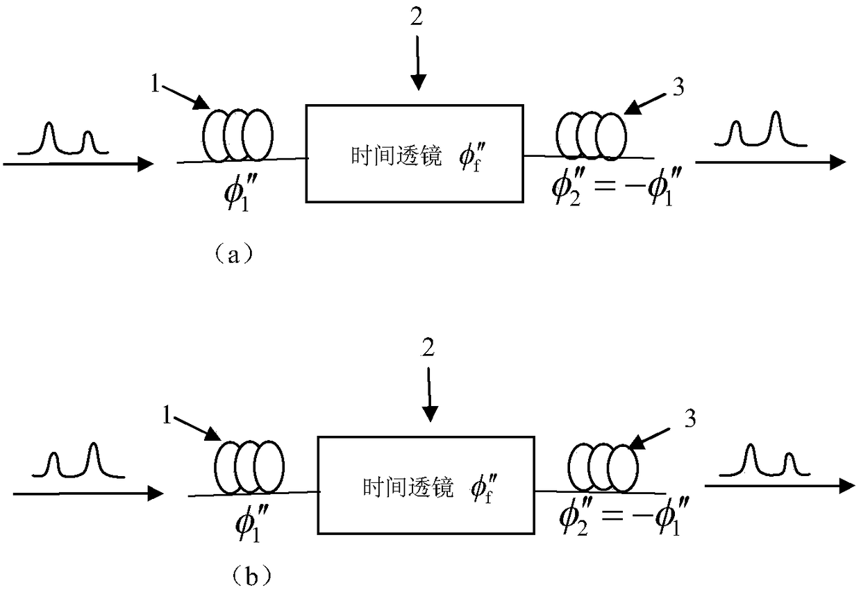
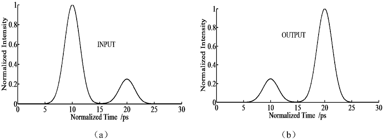
[0020] refer to Figure 1 ~ Figure 4 , an optical signal encryption / decryption system based on time lens imaging, including a time lens imaging subsystem; the time lens imaging subsystem is composed of an input segment optical fiber, a time lens and an output segment optical fiber, and two of the output segment optical fibers order dispersion φ 2 ″ and the second-order dispersion φ of the input fiber 1 "On the contrary, that is, φ 2 ″=-φ 1 "; The magnification M=φ of the time lens imaging subsystem 2 "φ 1 ″=-1; in all 0-yard time periods of the pump light sequence flow, the time lens effect does not occur, and the signal sequence in the time period covered by it remains unchanged; in all 1-yard time periods of the pump light sequence flow In , the time lensing e...


PUM


Abstract

The invention discloses an optical signal encryption / decryption system based on time lens imaging. The system comprises time lens imaging sub-systems. Each time lens imaging sub-system is composed of an input section optical fiber, a time lens and an output section optical fiber. The second-order dispersion phi''<2> of the output section optical fiber is opposite to the second-order dispersion phi''<1> of the input section optical fiber, namely the''<2> is equal to -phi''<1>. The amplification factor of each time lens imaging sub-system is M=phi''<2> / phi''<1>=-1. In all 0 code periods of time of pump light sequence streams, time lens effects will not be generated and signal sequences in covered periods of time of pump light are kept unchanged. In all 1 code periods of time of the pump light sequence streams, the time lens effects are generated and the signal sequences in the covered periods of time of the pump light are inverted. According to the optical signal encryption / decryption system based on time lens imaging provided by the invention, optical signals can be encrypted and decrypted, and the security of the system is high.

Description

technical field [0001] The invention relates to an optical signal encryption / decryption system constructed by using time lens imaging technology. Background technique [0002] Time lens refers to an optical device that can generate a second time phase shift for optical signals. For signal processing in the field of optical communication, the first choice is to use four-wave mixing (FWM) to achieve the time lens effect. The magnitude of the electric field is E s (t) and E p (t) The signal light and the pump light have FWM interaction, and the electric field amplitude of the idle wave generated idle light E idler Relative to the input signal light E s In terms of introducing a quadratic phase shift, this is the basic principle of FWM to produce temporal lensing effect. [0003] From the input fiber (the second order dispersion is φ 1 "=β 2s L s ), time lens (the focal length dispersion is φ f ″=-φ p " / 2=-β 2p L p / 2), output fiber (the second order dispersion is φ...

Claims


Application Information

Patent Timeline
Patent Type & Authority Patents(China)
IPC IPC(8): H04B10/85
CPCH04B10/85
Inventor 郭淑琴徐大财李伽任宏亮蒋佩兰
Owner ZHEJIANG UNIV OF TECH
Learn More