A Design Method for Ink Plug Hole Tool

A design method and hole plugging technology, applied in printed circuits, electrical components, printed circuit manufacturing, etc., can solve problems such as the difficulty of plugging holes with ink through holes, it is difficult to meet the requirements of filling holes, and the ability to plug holes cannot be improved. To achieve the effect of shortening the plugging time, improving the plugging efficiency, and increasing the plugging force

Active Publication Date: 2019-01-29
AOSHIKANG TECH CO LTD
View PDF4 Cites 0 Cited by
  • Summary
  • Abstract
  • Description
  • Claims
  • Application Information

AI Technical Summary

Problems solved by technology

[0002] As the number of PCB board layers increases and the thickness of the board gradually increases, in order to save wiring space, the aperture of the via hole is also getting smaller and smaller. Under this background, the problem of ink plugging in the via hole is becoming more and more difficult. Traditional The most common method of plugging holes is to use aluminum sheets to make screens or screen printing plug holes, but as the diameter of via holes becomes smaller and the depth of holes becomes deeper and deeper, it is difficult for this method to meet the requirements of hole filling, and it is impossible to plug the holes. full
[0003] At present, the design of the ink plug hole tool adopts the cylindrical hole of the aluminum sheet, and the aperture of the cylindrical hole of the aluminum sheet is adapted to the aperture size of the corresponding plug hole on the PCB board, so as to prevent printing offset. When printing, the cylindrical hole of the aluminum sheet The effective area after overlapping with the PCB hole is π, so the aperture of the cylindrical hole of the unilateral aluminum sheet cannot improve the plugging capacity (such as figure 1 and figure 2 shown)

Method used


Image

  • A Design Method for Ink Plug Hole Tool
  • A Design Method for Ink Plug Hole Tool
  • A Design Method for Ink Plug Hole Tool

Examples


Embodiment

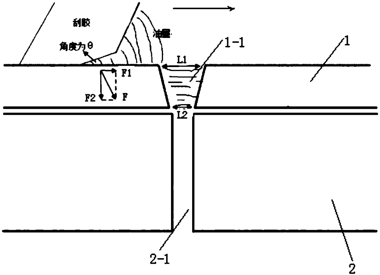
[0019] Refer to attached image 3 In this embodiment, the substrate 1 is placed above the PCB board 2, and an inverted tapered hole 1-1 is opened on the substrate 1. The position of the inverted tapered hole 1-1 is the same as that of the plug hole 2-1 on the PCB board 2. The position is adapted, the size of the lower surface of the inverted tapered hole 1-1 is adapted to the size of the plug hole 2-1, and the inclination F of the axial section of the inverted tapered hole 1-1 2 =F*cosθ, F is the scraper pressure, θ is the 1-1 slope angle of the inverted tapered hole;

[0020] When the squeegee is printed on the inverted tapered hole 1-1, the ink will be pushed into the inverted tapered hole 1-1, and the size of the pushing force is: F 合 -f, F 合 is the resultant force of the support force of the inclined plane and the pressure of the scraper, and f is the friction force;

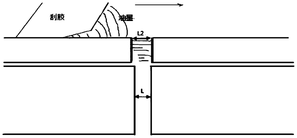
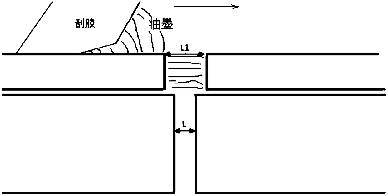
[0021] Scratch time: t 1 =L 1 / v,t 2 =L 2 / v, then t 1 >t 2 ;t 1 Printing time for cylindrical ...


PUM


Abstract

The invention provides a design method for a printing ink hole plugging tool. The design method comprises the steps that a base plate is placed on a PCB, an inverted-cone-shaped hole is formed in the base plate, the position of the inverted-cone-shaped hole is matched with that of a plug hole formed in the PCB, the size of the lower surface of the inverted-cone-shaped hole is matched with that of the plug hole, the axial section of the inverted-cone-shaped hole has the inclination degree, and therefore printing ink can be subjected to pushing force applying into the inverted-cone-shaped hole when squeegee is screen-printed to the inverted-cone-shaped hole. According to the design method, the hole plugging force is increased, the hole plugging fullness can be effectively guaranteed, the product quality is improved, and the good rate of finished products is guaranteed; the stressed area of the squeegee is increased, the hole plugging efficiency is effectively improved, and the hole plugging time is shortened.

Description

technical field [0001] The invention relates to the field of via green oil or resin hole filling in the process of PCB production, in particular to a design method for an ink plugging tool. Background technique [0002] As the number of PCB board layers increases and the thickness of the board gradually increases, in order to save wiring space, the aperture of the via hole is also getting smaller and smaller. Under this background, the problem of ink plugging in the via hole is becoming more and more difficult. Traditional The most common method of plugging holes is to use aluminum sheets to make screens or screen printing plug holes, but as the diameter of via holes becomes smaller and the depth of holes becomes deeper and deeper, it is difficult for this method to meet the requirements of hole filling, and it is impossible to plug the holes. full. [0003] At present, the design of the ink plug hole tool adopts the cylindrical hole of the aluminum sheet, and the aperture ...

Claims


Application Information

Patent Timeline
Patent Type & Authority Patents(China)
IPC IPC(8): H05K3/00
CPCH05K3/0094H05K2203/0139
Inventor 刘晴初龚德勋李刚
Owner AOSHIKANG TECH CO LTD
Why Eureka
Try Eureka