
Automatic soldering equipment capable of protecting transformer PINs and soldering method

An automatic welding and transformer technology, which is applied in welding equipment, metal processing equipment, auxiliary equipment, etc., can solve the problems of unguaranteed product quality, low soldering precision, low safety, etc., and achieve the advantages of automatic operation stability and structure Reasonable design and the effect of reducing labor costs

Pending Publication Date: 2021-01-08
DONGGUAN JIALONG HAIJIE ELECTRONICS TECH CO LTD
View PDF0 Cites 0 Cited by
  • Summary
  • Abstract
  • Description
  • Claims
  • Application Information

AI Technical Summary

Problems solved by technology

Traditional manual clamps are used to clamp the high-frequency transformer, so that the pins of the high-frequency transformer are inserted into the tin furnace for a certain period of time, and then taken out vertically. In this way, during the soldering process, the operator's hand is closer to the tin furnace, which is easier Burns, low safety, and only one high-frequency transformer can be soldered, which is time-consuming and labor-intensive, with low work efficiency and high production costs, and it is difficult to guarantee the quality of the solder, and the quality of the product cannot be guaranteed. The soldering depth of the copper wire leads is inconsistent. Affect the performance of the product
[0003] Later, automatic soldering machines appeared on the market, but this kind of automatic soldering machine still has shortcomings: directly soldering at high temperature after the metal terminal feet are glued with flux will cause the metal terminal feet to turn yellow, resulting in poor appearance of the solder
Also, as the number of times of soldering increases, the consumption of tin in the tin furnace increases, and the position and depth of soldering will gradually change, resulting in low soldering accuracy

Method used


Image

  • Automatic soldering equipment capable of protecting transformer PINs and soldering method
  • Automatic soldering equipment capable of protecting transformer PINs and soldering method
  • Automatic soldering equipment capable of protecting transformer PINs and soldering method

Examples


Embodiment Construction

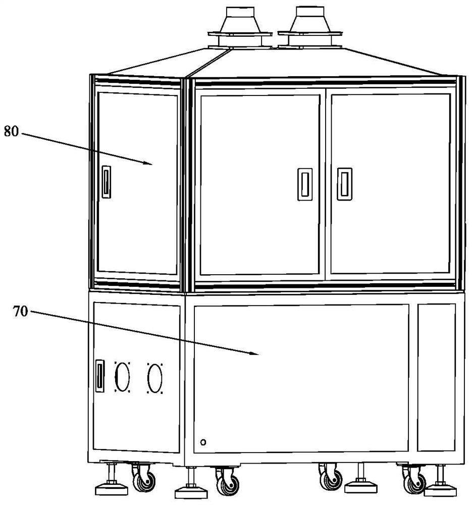
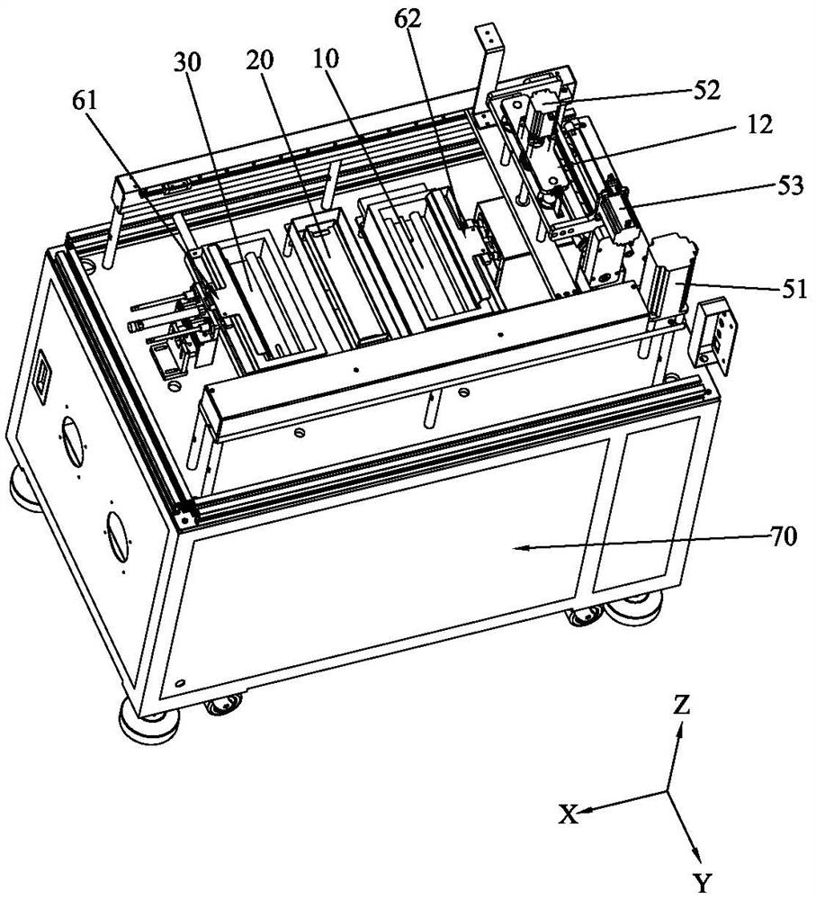
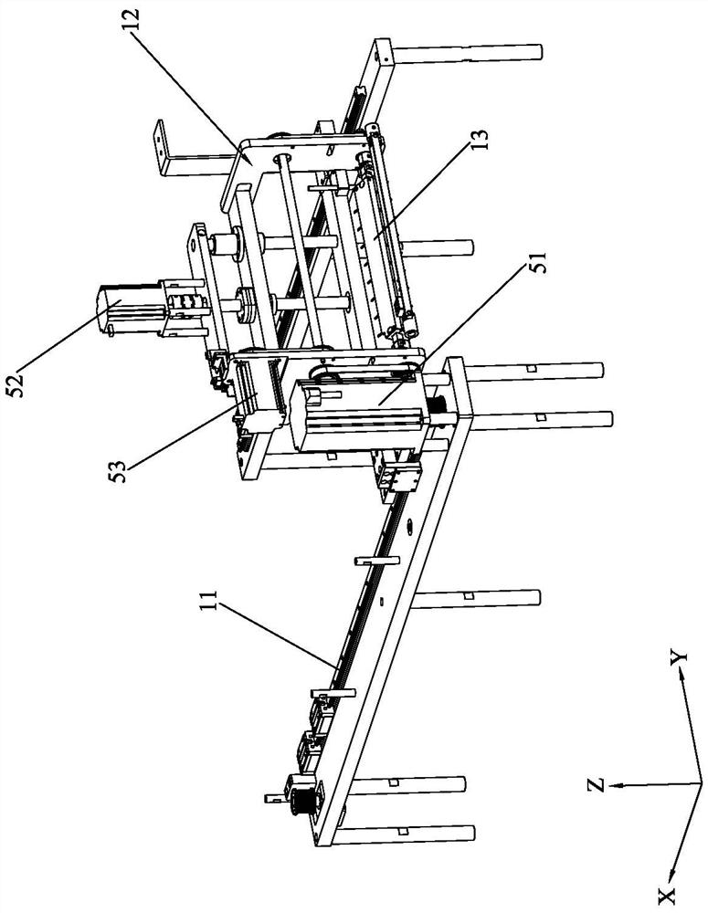
[0050] Please refer to Figure 1 to Figure 7 As shown, it shows the specific structure of the embodiment of the present invention.

[0051] An automatic soldering equipment that can protect the PIN pin of a transformer, including a jig transfer system, a high-temperature soldering system, a low-temperature soldering system, and a fluxing system;

[0052] The jig transfer system has a loading jig and a driving device that drives the loading jig to move; the high-temperature soldering system has a high-temperature soldering furnace 30; the low-temperature soldering system has a low-temperature soldering furnace 10; Furnace 20; the high-temperature solder furnace 30, low-temperature solder furnace 10, and flux furnace 20 are arranged in the X-axis direction of the loading jig; the drive device can selectively drive the loading jig to the flux furnace 20, low-temperature solder Furnace 10, high-temperature soldering furnace 30. When performing soldering operations, on the same m...


PUM


Abstract

The invention discloses automatic soldering equipment capable of protecting transformer PINs and a soldering method. The automatic soldering equipment capable of protecting the transformer PINs comprises a jig transferring system, a high-temperature soldering system, a low-temperature soldering system and a soldering flux system; the jig transferring system is provided with a loading jig and a driving device for driving the loading jig to move; the high-temperature soldering system is provided with a high-temperature soldering furnace; the low-temperature soldering system is provided with a low-temperature soldering furnace; the soldering flux system is provided with a soldering flux furnace; the high-temperature soldering furnace, the low-temperature soldering furnace and the soldering flux furnace are arranged in an X-axis direction of the loading jig; and the driving device selectively drives the loading jig to the soldering flux furnace, the low-temperature soldering furnace and the high-temperature soldering furnace. Therefore, by configuring the jig transferring system, the high-temperature soldering system, the low-temperature soldering system and the soldering flux system,when soldering operation is conducted, low-temperature soldering furnace soldering can be conducted before high-temperature soldering furnace soldering on a same machine base, so that the problem of yellowing of soldered transformer PINs in traditional technologies is effectively solved, and the condition of poor soldering of transformer PINs is improved.

Description

technical field [0001] The invention relates to the technology in the field of soldering machines, in particular to an automatic soldering equipment and a soldering method capable of protecting PIN pins of a transformer. Background technique [0002] At present, in the processing of electronic products, it is often necessary to use a soldering machine to solder the metal terminal feet of electronic components, that is, to place the metal terminal feet on the tin surface in the tin furnace so that the liquid tin can evenly and smoothly adhere to the metal terminal feet superior. Traditional manual clamps are used to clamp the high-frequency transformer, so that the pins of the high-frequency transformer are inserted into the tin furnace for a certain period of time, and then taken out vertically. In this way, during the soldering process, the operator's hand is closer to the tin furnace, which is easier Burns, low safety, and only one high-frequency transformer can be solder...

Claims


Application Information

Patent Timeline
Patent Type & Authority Applications(China)
IPC IPC(8): B23K3/00B23K3/08B23K1/00B23K1/008
CPCB23K3/00B23K3/08B23K1/00B23K1/008B23K1/0008
Inventor 阮诗扬周华平王健
Owner DONGGUAN JIALONG HAIJIE ELECTRONICS TECH CO LTD
Learn More