Engaging and disengaging mechanism of pen type syringe

A pen-type syringe and clutch mechanism technology, which is applied to syringes, infusion sets, etc., can solve the problems of inconvenient use and inability to quickly replace the material tube, and achieve the effect of convenient use.

Active Publication Date: 2016-12-14
中山汇丰医用包装科技有限公司
View PDF5 Cites 8 Cited by
  • Summary
  • Abstract
  • Description
  • Claims
  • Application Information

AI Technical Summary

Problems solved by technology

[0003] The purpose of the present invention is to provide a clutch mechanism for a pen-type injector that is easy to use and can quickly replace t...

Method used


Image

  • Engaging and disengaging mechanism of pen type syringe
  • Engaging and disengaging mechanism of pen type syringe
  • Engaging and disengaging mechanism of pen type syringe

Examples


Embodiment Construction

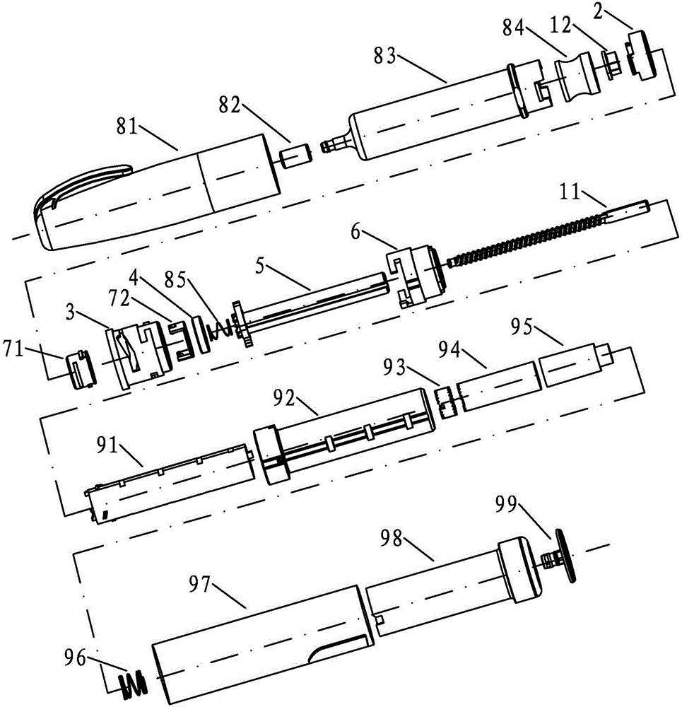
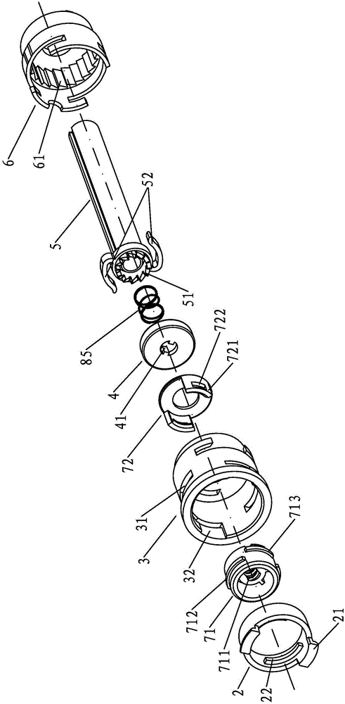
[0020] See figure 1 , is a three-dimensional exploded schematic diagram of a pen injector using the clutch mechanism of the pen injector according to the present invention, the pen injector includes a pen cap 81, sealing glue 82, material tube 83, piston 84, push head 12, guide ring 2. Connection block 71, buckle seat 3, axial push ring 72, clutch ring 4, clutch spring 85, transmission tube 5, connection seat 6, screw rod 11, coiled tube 91, casing 92, transfer gear cylinder 93, transmission gear Cylinder 94, transmission cylinder 95, tail spring 96, shell 97, knob 98, pressure head 99; wherein coil 91, sleeve 92, transfer gear cylinder 93, transmission gear cylinder 94, transmission cylinder 95, tail spring 96, shell 97 , the knob 98 and the pressure head 99 form a driving mechanism for driving the transmission tube 5 to rotate, and the driving mechanism is installed in the housing 97 .

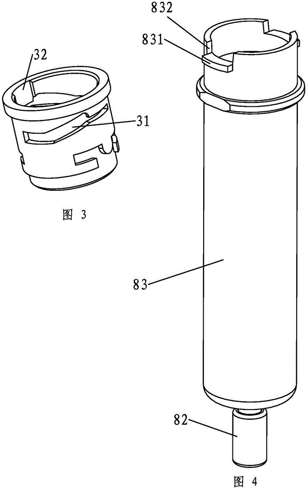
[0021] See image 3 , the buckle seat is provided with two symmetrical spiral guide gr...


PUM


Abstract

The invention relates to an engaging and disengaging mechanism of a pen type syringe. The engaging and disengaging mechanism is convenient to use and capable of rapidly replacing a charge pipe. The engaging and disengaging mechanism comprises a shell, a screw, a transfer pipe, the charge pipe and a driving mechanism driving the transfer pipe to rotate; the tail part of the transfer pipe of which the front end face is provided with engaging and disengaging teeth extends into the shell through the bottom of a connecting base to be connected with the driving mechanism, and an engaging and disengaging area is formed by the connecting base which is buckled with a buckle base and the buckle base in an enclosing mode; an engaging and disengaging spring, an engaging and disengaging ring and an axial push ring with two axial push feet are arranged in the engaging and disengaging area in sequence; teeth are arranged on the engaging and disengaging ring, and the engaging and disengaging teeth are arranged on the transfer pipe; the axial push feet on the axial push ring penetrate through the bottom of the buckle base to extend into an inner cavity of the buckle base, the screw penetrates through the engaging and disengaging ring and the axial push ring to be coupled with an internal thread in the buckle base and then engaged with a push head for fixation; a convex rib extending into an axial groove of the screw surface is arranged on the engaging and disengaging ring, the front part of the charge tube internally provided with a piston extends into the inner cavity of the buckle base, and the opening of the charge tube is provided with engaging wings clamped into spiral guide grooves of the buckle base.

Description

technical field [0001] The invention relates to a clutch mechanism of a pen type injector. Background technique [0002] In the Chinese patent application with the announcement number CN201324413Y announced on October 14, 2009, a quantitative adjustable pen injector is disclosed, including a fixed tube, a push head, a sleeve, a clutch sleeve, a rotating tooth, a screw, and a transmission tube. , stop ring, fixed ring, coil, relay gear, transmission gear, sleeve, etc., it adjusts the position of the coil relative to the sleeve by rotating the tail end of the coil so as to adjust the preloading dose during injection. During the process of the coiled tube being pressed inward, the coiled tube drives the intermediate gear cylinder, the transmission gear cylinder, the transmission tube, the rotating gear and the screw to rotate, so that the screw is pushed forward relative to the sleeve and the injection placed in the fixed tube is given quantitatively. Human body injection; it ...

Claims


Application Information

Patent Timeline
IPC IPC(8): A61M5/178A61M5/31
CPCA61M5/178A61M5/31
Inventor 邓源基
Owner 中山汇丰医用包装科技有限公司
Why Eureka
Try Eureka