
Frame robot welding system

A robot welding and robot technology, applied in welding equipment, auxiliary welding equipment, welding/cutting auxiliary equipment, etc., can solve the problems of reducing welding accuracy, the influence of welding accuracy and efficiency group on accuracy, and reducing welding efficiency.

Active Publication Date: 2016-12-14
斯图加特航空自动化(青岛)有限公司
View PDF6 Cites 18 Cited by
  • Summary
  • Abstract
  • Description
  • Claims
  • Application Information

AI Technical Summary

Problems solved by technology

Existing welding robots weld the tank car frame generally through the robot sliding table to drive the robot to walk and cooperate with the rotation of the positioner to realize the welding of the tank body. In this way, the welding accuracy and efficiency of the robot are greatly affected by the pair accuracy of the tank car frame. The accuracy will be reduced (the robot welding torch cannot find the weld seam), and the welding efficiency will be reduced accordingly

Method used


Image

  • Frame robot welding system
  • Frame robot welding system
  • Frame robot welding system

Examples


Embodiment Construction

[0031] In order to make the object, technical solution and advantages of the present invention clearer, the present invention will be described in detail below in conjunction with the accompanying drawings and specific embodiments.

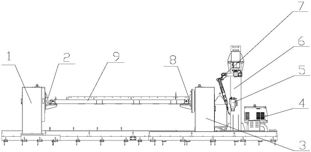
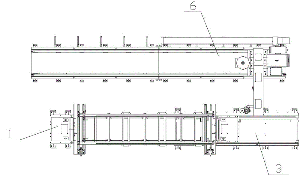
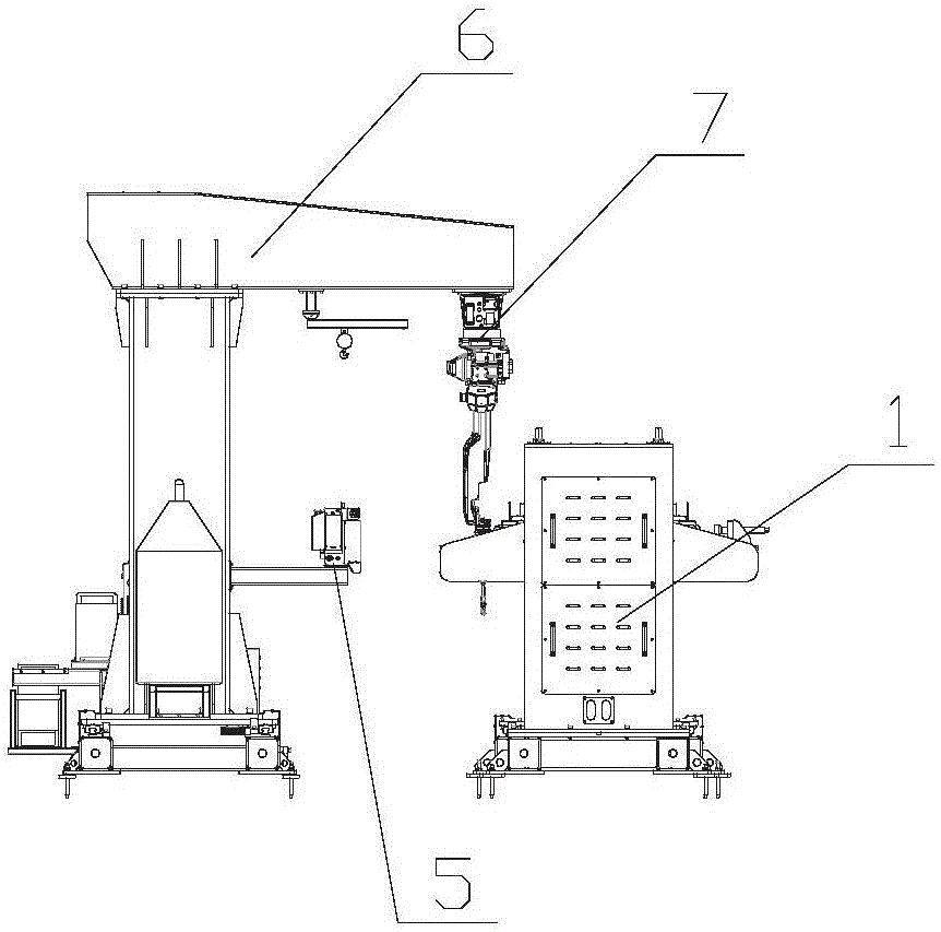
[0032] Such as Figure 1-3 As shown, a frame robot welding system provided by the present invention includes a positioner head frame 1, a head end tooling fixture 2, a positioner tail frame 3, a robot sliding table walking mechanism 6, a robot welding system 7, and a welding power supply And the end tooling fixture 8, wherein the head end tooling fixture 2 and the tail end tooling fixture 8 are rotatably installed on the flanges of the positioner head frame 1 and the positioner tail frame 3 respectively, for clamping the vehicle frame 9. The robot sliding table running mechanism 6 is arranged on one side of the positioner head frame 1 and the positioner tail frame 3, and the robot welding system 7 is arranged on the robot sliding table running me...


PUM


Abstract

The invention relates to a robot welding system, in particular to a frame robot welding system. The frame robot welding system comprises a position changer headstock, a head end tool clamp, a position changer tailstock, a robot sliding table traveling mechanism, a robot welding system and a tail end tool clamp, wherein the head end tool clamp and the tail end tool clamp are respectively mounted on flange plates of the position changer headstock and the position changer tailstock rotatably and are used for clamping a frame; the robot sliding table traveling mechanism is arranged on one side of the position changer headstock and the position changer tailstock; and the robot welding system is arranged on the robot sliding table traveling mechanism, and is driven by the robot sliding table traveling mechanism to linearly move along an X axis. The servo-driven sliding table traveling mechanism can linearly move along the X axis, and by rotation of the workpiece driven by a position changer and a robot welding gun, welding at various angles is realized.

Description

technical field [0001] The invention relates to a robot welding system, in particular to a vehicle frame robot welding system. Background technique [0002] With the widespread application of robots in industry, more and more factories have begun to use robots to weld large workpieces composed of plates. Due to the large mass of the workpiece itself, the manual assembly and welding process is very cumbersome, and the workpiece cannot be turned over. It is impossible to achieve fast and accurate welding manually. At present, positioners and robots are generally used for welding work, that is, the workpieces to be welded are fixed by the fixtures on the positioners, and the positions of the workpieces are adjusted by the positioners to make the workpieces reach a suitable position. The welding posture can meet the welding requirements of the robot. [0003] The welding robot runs according to the preset program. The robot clamps the welding torch to the beginning of the weld...

Claims


Application Information

Patent Timeline
Patent Type & Authority Applications(China)
IPC IPC(8): B23K37/047B23K37/02B23K37/00
Inventor 肖宁邵立早熊星霖薛海涛廖运雄崔西明初建松
Owner 斯图加特航空自动化(青岛)有限公司
Learn More