Flat membrane bioreactor

A bioreactor, flat membrane technology, applied in biological treatment devices, biological water/sewage treatment, chemical instruments and methods, etc., can solve the problems of reducing membrane flux, foaming and foaming in the fermentation process, and reducing contamination. The possibility of scale clogging, the overall structure is simple, the effect of improving the mass transfer efficiency

Inactive Publication Date: 2016-12-14
JIANGSU LVYANG BIOLOGICAL ELECTRONICS ENG CO LTD
View PDF2 Cites 0 Cited by
  • Summary
  • Abstract
  • Description
  • Claims
  • Application Information

AI Technical Summary

Problems solved by technology

[0003] As a kind of membrane bioreactor, the flat membrane bioreactor has also been widely studied and applied, but the yield of this kind of reactor is relatively low, or the cost is too high due to the use of special membranes
Moreover, the stability and reliability of the entire reactor can be reduced after membrane fouling, and the membrane flux is reduced, thereby reducing the treatment efficiency of the reactor. The fouling of the membrane is mainly caused by the composition of the reactor (water-soluble organic matter, feed colloidal particles, cell lysis and inorganic precipitates)
[0004] In addition, with the application of new industrial fermentation technologies, large-vessel bioreactors have been widely promoted, and foams appear during the fermentation process, which often have adverse effects on production.
Due to the obstacle of foaming, the gas phase in the reactor is occupied by foam, and the amount of material is reduced, which undoubtedly reduces the volumetric efficiency of the reactor, and often due to untimely defoaming, the foam rises and forms a "bubble" phenomenon, resulting in the The efficiency of the membrane module is greatly reduced

Method used


Image

  • Flat membrane bioreactor

Examples


Embodiment

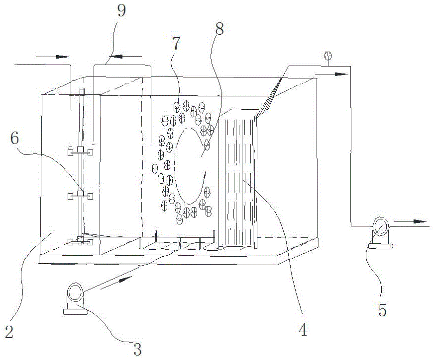
[0018] The flat membrane bioreactor of the present embodiment, such as figure 1 As shown, it includes an anaerobic tank 2, an aerobic tank 8 and a membrane module 4 connected in sequence. The aerobic tank 8 is supplied with air by the air pump 3, and the membrane module 4 is discharged by the suction pump 5. The anaerobic tank 2 is provided with a water inlet, and a stirring shaft 6 is vertically arranged in the anaerobic tank 2, and a plurality of stirring paddles are arranged at intervals on the stirring shaft 6, and the lower end of the stirring shaft 6 extends To the bottom of the anaerobic pool 2, the inner wall of the anaerobic pool 2 is sequentially provided with multiple sections of spiral channels (not shown in the figure) from top to bottom, and each section of the spiral channel is fixed on the inner wall of the anaerobic pool by multiple pieces The helical blades are spliced ​​around, and each section of the helical channel is formed with a through channel for acco...


PUM

PropertyMeasurementUnit
pore sizeaaaaaaaaaa

Abstract

The invention relates to a flat membrane bioreactor. The flat membrane bioreactor comprises an anaerobic pool, an aerobiotic pool and a membrane component which are successively connected with each other, wherein a water inlet is arranged on the anaerobic pool; a stirring shaft is vertically arranged in the anaerobic pool; a plurality of stirring blades are arranged on the stirring shaft at intervals; the lower end of the stirring shaft extends to the bottom of the anaerobic pool; multiple sections of spiral channels are successively arranged on an inner wall of the anaerobic pool at intervals from top to bottom; each section of spiral channel is formed by surrounding and splicing a plurality of spiral blades fixed on the inner wall of the anaerobic pool; each section of spiral channel is equipped with a penetrating channel for accommodating the stirring blades; a filtering screen is wrapped on the periphery of the membrane component; the filtering screen is of 30-50 meshes; the aperture of the filtering screen is 0.4-0.5mm; a backflow pipeline is arranged between the anaerobic pool and the aerobiotic pool; a suspended filler fills the aerobiotic pool; an ultrasonic generator is arranged on the side wall of the aerobiotic pool. The flat membrane bioreactor has a simple structure and is high in production efficiency.

Description

technical field [0001] The invention relates to a flat membrane bioreactor, which belongs to the technical field of sewage treatment. Background technique [0002] Membrane bioreactors are widely used in the field of sewage treatment and reuse. Membrane bioreactors combine biomass and membranes to convert the supplied substances into biological substances. It can be used for biological reactions, for example, to produce useful substances (such as drugs , antibodies or vaccine components), the bioconversion of organic waste into biomass or biofuel, or the remediation of toxic waste, including the degradation of toxic chemicals into inert or non-bioavailable forms, and the precipitation or reduction / oxidation of heavy metals, etc. . [0003] Flat membrane bioreactor, as a kind of membrane bioreactor, has also been widely studied and applied, but the yield of this kind of reactor is relatively low, or the cost is too high because of the use of special membrane. Moreover, the ...

Claims


Application Information

Patent Timeline
Patent Type & Authority Applications(China)
IPC IPC(8): C02F3/30
CPCC02F3/30C02F2203/006C02F2303/22C02F2303/24
Inventor 郭忠司剑
Owner JIANGSU LVYANG BIOLOGICAL ELECTRONICS ENG CO LTD
Why Eureka
Try Eureka