
Foundation pit supporting method for ground tube pile anchor frame

A foundation pit support and frame technology, which is applied in excavation, foundation structure engineering, construction, etc., can solve the problems of limited anti-overturning capacity of double-row piles, inability to construct anchor cables, and large deflection of steel supports, so as to shorten the construction period and reduce the The effect of high cost and high cost

Active Publication Date: 2016-12-14
河北亨远建设工程有限公司
View PDF7 Cites 3 Cited by
  • Summary
  • Abstract
  • Description
  • Claims
  • Application Information

AI Technical Summary

Problems solved by technology

[0003] The above three foundation pit support schemes have their own limitations and are not applicable in some specific environments: the first method of rowing piles and prestressed anchor cables requires that the foundation of surrounding buildings should not be too deep, otherwise the anchor cables cannot be constructed ; The second row of piles plus internal support method is suitable for narrow and long foundation pits, and the direction of steel support should not be too wide, otherwise the deflection of the steel support will be too large; the third method of double row piles, compared with single row pile construction The cost is high, the construction period is long, and the anti-overturning ability of double-row piles is limited

Method used


Image

  • Foundation pit supporting method for ground tube pile anchor frame
  • Foundation pit supporting method for ground tube pile anchor frame
  • Foundation pit supporting method for ground tube pile anchor frame

Examples


Embodiment Construction

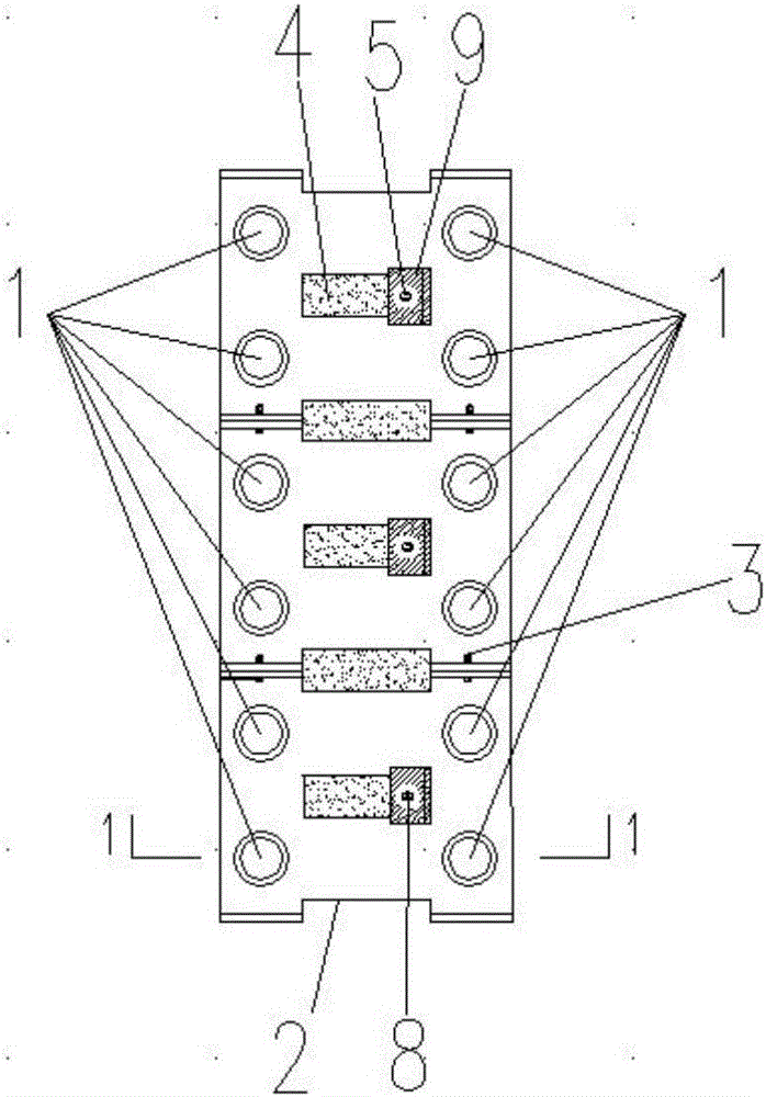
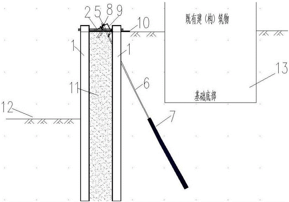
[0022] The following is attached Figure 1-4 The present invention is described in further detail.

[0023] A ground pipe pile anchor frame foundation pit support method, the implementation process of the method is as follows, first, the prefabricated assembled frame composite beam (2), laying pile holes in the assembled frame composite beam (2), the size of the pile holes Calculated according to design specifications. Secondly, the prefabricated frame composite beam (2) is poured on the leveled construction site by using a low-strength concrete cushion. A static pressure construction method is adopted to press concrete pipe piles (1) with a diameter of 400 mm to 600 mm into the formation in the reserved holes of the assembled frame composite beam (2). The prestressed anchor cable (5) is laid in the reserved square hole (4) between the front and rear rows of piles, the anchor cable passes through the reserved anchor cable hole of the anchor cable reaction seat (9) and the pr...


PUM


Abstract

The invention discloses a foundation pit supporting method for a ground tube pile anchor frame. According to the method, concrete tube piles and pre-stressed anchor cables are used as the foundation. The method mainly refers to a foundation pit supporting method in which the adjacent building foundation embedded depth is high, the distance away from a foundation pit is short, the foundation pit side wall deformation requirement is high, and conventional anchor cable and steel shotcrete supporting cannot be achieved. By the adoption of the method, two rows of concrete tube piles are arranged around the foundation pit to be excavated, and the pre-stressed anchor cables which forms an angle alpha downwards are arranged between the front row piles and the rear row piles of the top of the foundation pit. Collision of the anchor cables with adjacent existing buildings (structures) is avoided under the condition of guaranteeing rigidity of the tube pile structure. The concrete tube piles are used for replacing reinforced concrete piles, and thus cost can be effectively reduced. The method is used for foundation pit supporting, foundation pit side wall deformation can be reduced, and the stability against overturning of the foundation pit can be enhanced. The security coefficient of the buildings (structures) around in the foundation pit construction process is increased, and meanwhile the purposes of shortening the construction period and reducing the cost are achieved.

Description

technical field [0001] The invention belongs to the technical field of civil engineering construction, and is mainly used for adjacent buildings (structures) whose foundations are deeply buried and are relatively close to foundation pits, and require high deformation of the side walls of foundation pits, where conventional anchor pulling and internal support construction cannot be carried out. Foundation pit support engineering. Background technique [0002] During the excavation of urban foundation pits, since there are many existing buildings (structures) around the foundation pits, and the foundations of the buildings (structures) are relatively deep, excavation on slopes is not allowed. In order to ensure the stability of the foundation pit, To limit the horizontal displacement and settlement of the soil around the foundation pit, a suitable foundation pit support scheme must be adopted. In practice, the commonly used foundation pit support methods include: ①The method o...

Claims


Application Information

Patent Timeline
IPC IPC(8): E02D17/04
CPCE02D17/04
Inventor 姚爱军周一君吕科验翟玉新
Owner 河北亨远建设工程有限公司
Learn More